Do you have a question about the Sony ZS-D10 and is the answer not in the manual?
Details US model audio power output and total harmonic distortion.
Provides specifications for the CD player, including laser diode properties and spindle speed.
Lists frequency ranges, tuning bands, and antenna types for the radio section.
Covers speaker type, input/output details, and power output for different regions.
Specifies power sources for the system and remote control, and dimensions/mass.
Covers chip component replacement, flexible circuit board repair, and general safety.
Outlines the process for checking AC leakage current from exposed metal parts to ground.
Discusses characteristics of unleaded solder and safe power source usage.
Advises on unplugging the unit and removing batteries when not in use.
Provides precautions for handling the optical pick-up block and checking laser diode emission.
Details the procedure for checking laser diode emission and focus search operation.
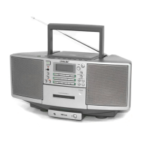
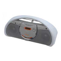
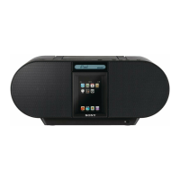
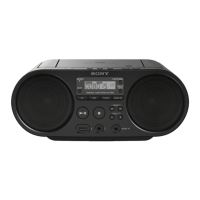
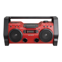
Identifies and describes the location of various controls on the unit and remote.
Explains how to turn the unit on/off, adjust volume, use headphones, and interpret the display.
Details controls for CD lid light, audio emphasis, and bass reinforcement.
Illustrates the sequential steps for disassembling the unit.
Details the removal of major sub-assemblies like Net Sub Assy, Cover (CD) Assy, LCD Assy, Optical Block, and Pick-up.
Covers disassembly of the Cabinet (Rear), Speakers, Tuner Board, and Chassis Section.
Instructions for removing the Door SW Board and Main Board.
Outlines the sequential steps for assembling the unit.
Steps for assembling the CD lid, cover, spring, and collar.
Instructions for installing the gear and damper mechanisms.
Notes on precautions, setting MEGA BASS OFF, and general adjustment procedures.
Specific adjustment procedures for the AM/MW/LW bands.
Specific adjustment procedures for the FM band.
Identifies adjustment points and connecting locations on the Tuner Board.
Instructions for entering and exiting CD test mode.
Details checks for focus bias and traverse operations using test discs.
Illustrates functional blocks and signal paths for CD, Tuner, and Main sections.
Explains diagram notations, board layouts, and their locations.
Shows printed wiring layouts for CD, Tuner, and Panel sections.
Presents schematic circuit diagrams for CD, Tuner, Panel, and Audio/Power sections.
Illustrates printed wiring layouts for the Main and Audio/Power Supply sections.
Displays typical waveforms observed on the CD Board during operation.
Shows characteristic waveforms measured on the Tuner Board.
Presents waveform examples from the Main Board for diagnostic purposes.
Internal block diagram for IC701 on the CD Board.
Internal block diagram for IC702.
Internal block diagram for IC1 on the Tuner Board.
Internal block diagram for IC2 on the Tuner Board.
Internal block diagram for IC321 on the Main Board.
Details the pin functions for IC801, the System Controller on the Main Board.
Continues the pin function details for IC801 on the Main Board.
Exploded view showing the components of the Net Sub Assy.
Exploded view illustrating the parts of the Cover (CD) section.
Exploded view showing the components of the Cabinet (Rear) section.
Exploded view of the first part of the Cabinet (Front) section.
Exploded view of the second part of the Cabinet (Front) section.
Exploded view of the third part of the Cabinet (Front) section.
Exploded view of the fourth part of the Cabinet (Front) section.
Exploded view of the fifth part of the Cabinet (Front) section.
Exploded view detailing the Optical Pick-up Section.
Lists components for the CD Board, including capacitors, connectors, ICs, and resistors.
Lists various components for the Tuner Board, such as capacitors, diodes, ICs, and resistors.
Lists components for the Main Board, including capacitors, ICs, resistors, and transistors.
Lists components for Control (Play, Power, Vol) and Panel (DC Jack, Door SW, Jack, LCD, LED) boards.
Lists components for the Power Amp Board.
| Equalizer | Yes |
|---|---|
| Sleep timer | No |
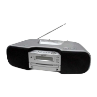
| Device type | Portable CD player |
| Product color | Silver |
| Preset stations quantity | 40 |
| Dimensions (WxDxH) | 530 x 127 x 195 mm |
| Weight | 2500 g |
|---|