EasyManua.ls Logo

Sony ZS-D55 Service Manual

Sony ZS-D55
56 pages
To Next Page IconTo Next Page
Page #1 background imageLoading...
Page #1 background image
Ver 1.0 2000.07
ZS-D55
SERVICE MANUAL
PERSONAL AUDIO SYSTEM
SPECIFICATIONS
AEP Model
UK Model
Tourist Model
TAPE Model Name Using Similar Mechanism NEW
Section Tape Transport Mechanism Type MF-ZSD55
CD
Model Name Using Similar Mechanism ZS-D50
Section
MD Mechanism Type CDM-2411AAA
Optical Pick-up Type DAX-01A2
– Continued on page 2 –
CD player section
System
Compact disc digital audio system
Laser diode properties
Material: GaAlAs
Wave length: 780 nm
Emission duration: Continuous
Laser output: Less than 44.6 µW (This output is the value measured
at a distance of about 200 mm from the objective lens surface on the
optical pick-up block with 7 mm aperture.)
Spindle speed
200 r/min (rpm) to 500 r/min (rpm) (CLV)
Number of channels
2
Frequency response
20 - 20 000 Hz +0.5/–1.2 dB
Wow and flutter
Below measurable limit
Radio section
Frequency range
FM : 87.5 - 108 MHz
MW : 531 - 1602 kHz
LM : 153 - 279 kHz
IF
FM : 10.7 MHz
MW/LW : 450 kHz
Aerials
FM : Telescopic aerial
MW/LW : Built-in ferrite bar aeraial
Cassette-corder section
Recording system
4-track 2 channel stereo
Fast winding time
Approx. 112 s (sec.) with Sony cassette C-60
Frequency response
TYPE I (normal): 50 - 15 000 Hz
General
Speaker
Full range: 8 cm (3 1⁄4 in.) dia., 12 ,
cone type x 2
Input
LINE IN jack (stereo minijack)
Minimum input level 138 mV
Outputs
Headphones jack (stereo minijack)
For 8 - 32 impedance headphones
LINE OUT jack (stereo minijack)
Rated output level 138 mV at load impedance
47 k
OPTICAL DIGITAL OUT (CD) (optical output connector)
Wavelength: 630 - 690 nm
Maximum power output
5 W + 5 W

Other manuals for Sony ZS-D55

Question and Answer IconNeed help?

Do you have a question about the Sony ZS-D55 and is the answer not in the manual?

Sony ZS-D55 Specifications

General IconGeneral
BrandSony
ModelZS-D55
CategoryStereo System
CD PlaybackYes
Radio TunerYes
Tuner BandsAM/FM
Cassette PlaybackYes
Speaker Configuration2.0
Dimensions300 x 270 x 135 mm
Weight2.3 kg
Frequency Response50 Hz - 20 kHz
Signal-to-Noise Ratio70 dB
ConnectivityAuxiliary input

Summary

Specifications

Service Notes and Precautions

Handling the Optical Pick-up Block

Provides critical instructions for safely handling the optical pick-up.

Laser Diode Emission Check

Details the procedure and safety measures for checking laser diode output.

Rear Panel and Remote Commander

Remote Commander Functions

Explains the operation of each button on the provided remote control.

Disassembly - Main Section

3-1. Cabinet Rear/Front Assembly

Step-by-step guide for disassembling the main rear and front cabinet parts.

Disassembly - Boards

3-2. Power, P/T In/Out, Battery Boards

Instructions for removing the power supply and battery related circuit boards.

Disassembly - Audio and CD Boards

3-6. CD Board Removal

Guide for removing the main circuit board for the CD player mechanism.

Disassembly - RF, Belts, and CD Chassis

3-14. CD Chassis Assembly Removal

Steps for disassembling the entire CD player chassis assembly.

Disassembly - CD Tray and Pick-up

3-18. Optical Pick-up Block Removal

Steps for removing the optical pick-up assembly and relay board.

Test Mode Operations

CD Section Test Mode

Instructions for entering and performing tests on the CD player section.

RF Level and Jitter Check

Details the procedure for measuring RF signal level and jitter for the CD.

Adjustments - Mechanical

Tape Recorder Section Precautions

Important precautions before performing mechanical adjustments on the tape recorder.

Adjustments - Electrical

Tape Recorder Electrical Adjustments

Procedures for electrical adjustments, including input/output levels and head alignment.

Tuner and Tape Adjustments

Tape Speed Adjustment

Guide for adjusting the tape playback speed using a frequency counter.

Diagrams and IC Terminals

6-1. Explanation of IC Terminals

Lists and describes the function of each pin for various ICs used in the unit.

Printed Wiring Boards - Main Section

6-4. Printed Wiring Boards (Main Section)

Shows the layout and component placement for main section circuit boards.

Schematic Diagrams - Main Section

6-5. Schematic Diagram (Main Section)

Detailed schematic illustrating the electronic circuitry of the main unit.

Schematic Diagrams - CD Section

6-6. Schematic Diagram (CD Section)

Detailed schematic for the CD player circuitry.

Waveforms (CD Section)

Illustrates key waveforms measured at different points in the CD section.

Printed Wiring Boards - CD Section

6-7. Printed Wiring Boards (CD Section)

Shows component layout for the CD section circuit boards.

Printed Wiring Boards - Control Section

6-8. Printed Wiring Boards (Control Section)

Displays the layout for control section circuit boards.

Schematic Diagrams - Control Section

6-9. Schematic Diagram (Control Section)

Detailed schematic for the unit's control circuitry.

Printed Wiring Boards - Tuner Section

IC Block Diagrams - Main Section

IC Block Diagrams - CD Section

IC Block Diagrams - Tuner Section

Exploded Views - Rear Section

Exploded Views - Front Section

Exploded Views - CD Block Section

Exploded Views - Mechanism Deck (Part 1)

Exploded Views - Mechanism Deck (Part 2)

Exploded Views - CD Section

Exploded Views - Optical Pick-up Section

7-8. Optical Pick-up Section

Exploded view of the optical pick-up assembly and its constituent parts.

Electrical Parts List - Capacitors

Capacitors

Comprehensive list of capacitors, including types, values, and ratings.

Electrical Parts List - Resistors, ICs, Transistors, Diodes

Resistors

List of all resistors used, with part numbers and values.
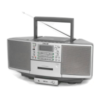
Related product manuals