Form 830 (03.13) ©SOR Inc.
5/12
120 VAC (651K7)
Remove cover.
Observe all applicable electrical codes and recognized wiring practices.
Remove two #4 mounting screws and slide out PC board to expose green ground screw
(Internal Primary Equipment Ground/Earth) in base of housing.
Connect ground wire to green ground screw on base of housing.
(Ground wire should be a minimum of 18-AWG.)
Reposition PC board, replace and tighten mounting screws. Ensure that banana
plug on sensor lead wire is secure in sensor jack.
Connect hot line power wire (typically black)
to L1 position on screw clamp terminal block.
Connect neutral line power wire (typically white)
to N position on screw clamp terminal block.
Replace cover.
Apply power as desired.
240 VAC (651K8)
Perform Steps 1 through 6 above.
Connect second hot line power wire
(typically red) to L2 position.
Perform Steps 8 and 9 above.
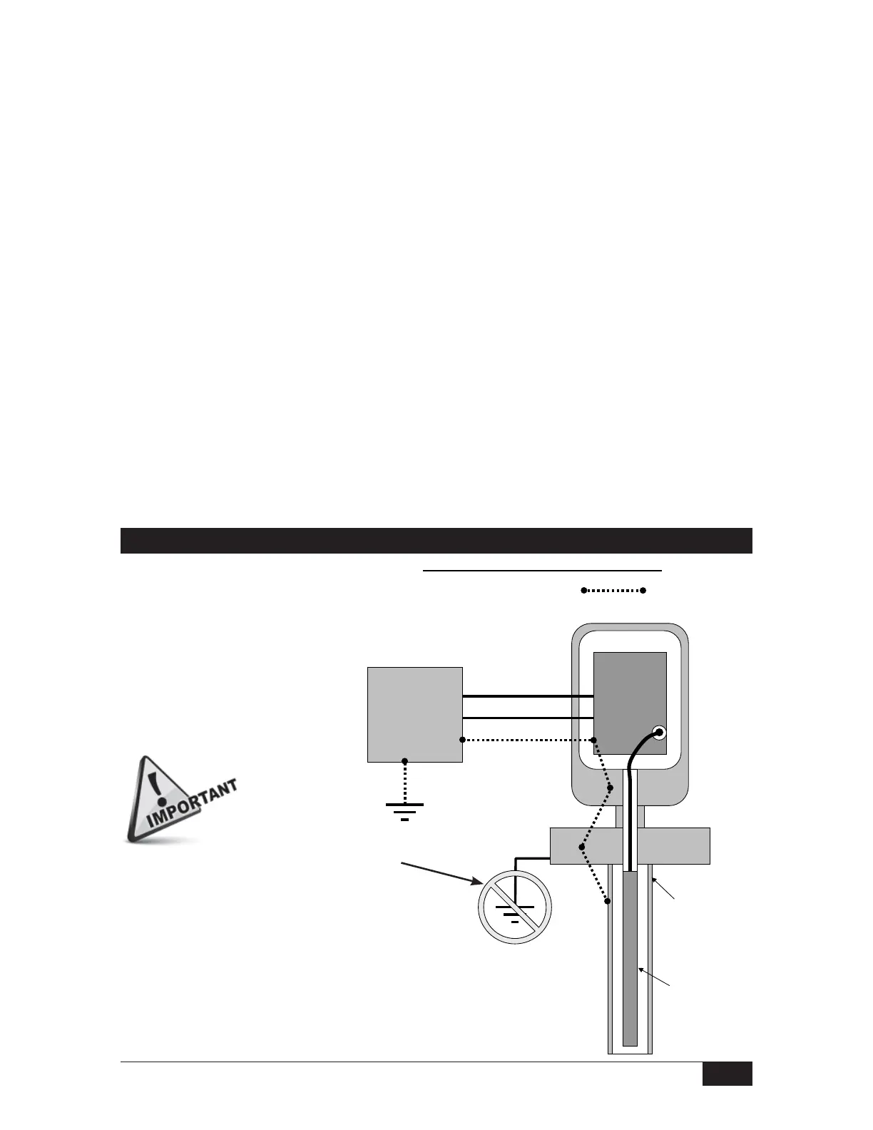
SOR RF Probe Grounding Scheme
12 VDC (651K5)
24VDC (651K6)
Perform Steps 1 through 5 above if a
case or equipment ground wire is pro-
vided for connection to earth ground.
Connect positive line power wire to
screw clamp terminal marked (+).
Connect negative line power wire to
screw clamp terminal marked (-).
Replace cover.
Apply power as desired.
SOR RF Probe Grounding Scheme
Critical Grounding Path =
Circuit
Board
Line
Neutral
Ground
Electronics
Housing
Power Supply
Line
Neutral
Ground
Process
Connection
SOR Supplied
Stilling Well
(optional)
Probe Center
Conductive Element
IMPORTANT! Do not
provide separate earth
grounding for the process
connection. This can create
a parallel grounding circuit
that will impair operation
and calibration.
Do not provide separate earth grounding
for the process connection. This can
create a parallel grounding circuit
that will impair operation and calibration.
 Loading...