6/12
Form 830 (03.13) ©SOR Inc.
Fail-Safe Mode
The fail-safe mode on either rising or falling level can be easily changed in the field. See
procedure and chart below.
NOTE: Upon loss of power, or some component failures, the output relay is de-energized andits
contacts return to the “shelf position” NC (Normally Closed) to signal an alarm condition regard-
less of process level.
Disconnect line power supply.
Remove the housing cover.
Determine whether switched external circuit must open or close (make or break) upon
loss of power to the instrument.
Determine whether switched external circuit must open or close (make or break) at a
discrete level on rising or falling level when the instrument is powered.
High-Level Fail Safe means the output relay will de-energize under high level conditions
and alarm a high-level condition upon loss of power. Conversely, Low-Level Fail Safe
means the output relay will de-energize under low-level conditions and alarm a
low-level condition upon loss of power.
The terminal block is labeled for a de-energized relay. Connect external circuit lead wires
to terminal block for desired logic. See chart below.
Use needle-nose pliers to switch JP1 to Position A (lower) or Position B (upper) to
change fail-safe mode.
Replace housing cover.
Connect line power supply as shown on pages 4 and 5.
Electrical power must be disconnected from explosion-proof models before
the cover is removed. Failure to do so could result in severe personal injury
or substantial property damage.
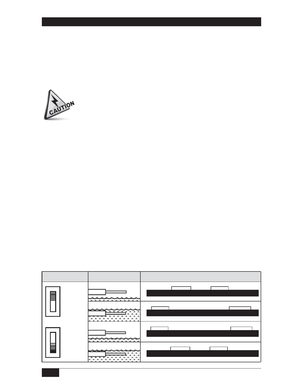
Continuity Chart
Fail Safe
LO
Fail Safe
HI
NC1 C1 NO1 NO2 C2 NC2
NC1 C1 NO1 NO2 C2 NC2
NC1 C1 NO1 NO2 C2 NC2
NC1 C1 NO1 NO2 C2 NC2
Relay
de-energized
on high level
Relay
de-energized
on low level
Relay De-Energized
Relay De-Energized
Relay Energized
Switch Position Process Level Terminal Continuity
Relay Energized
 Loading...