Registered Quality System to ISO 9001 | 913-888-2630 | SORInc.com
4/16
Form 281 (05.18) ©SOR Inc.
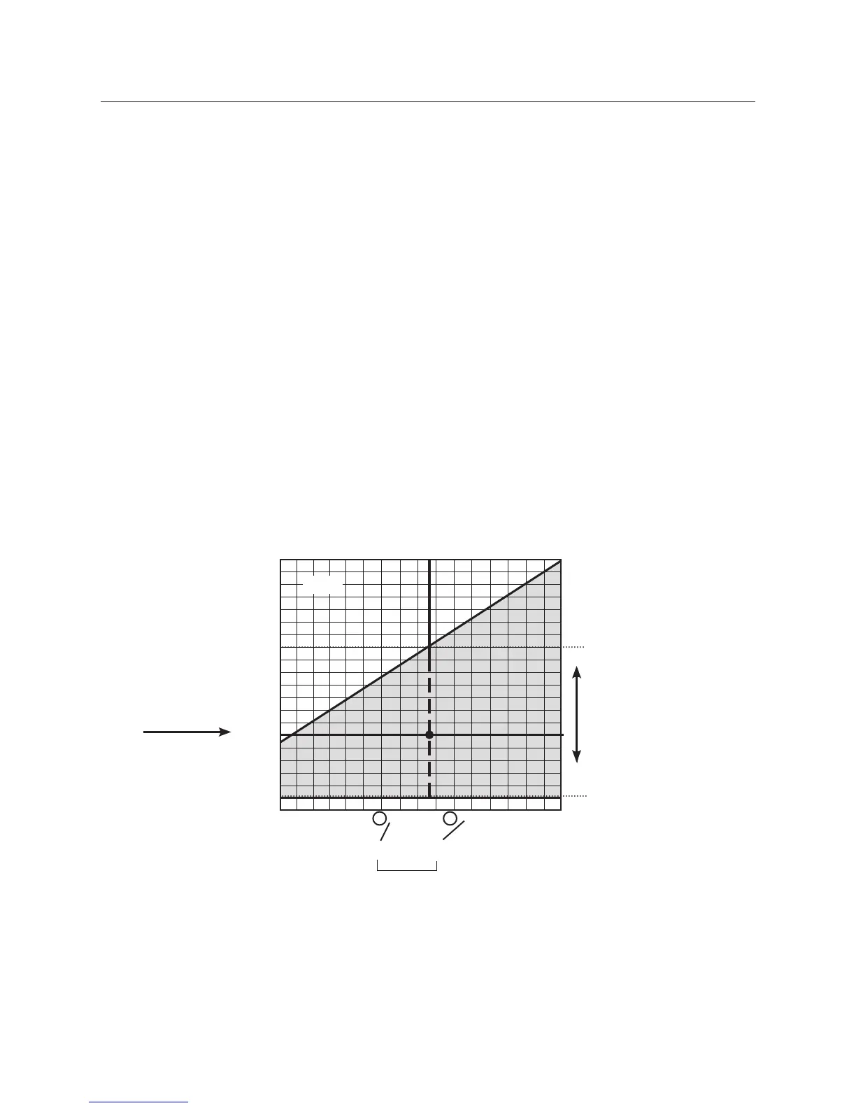
Six adjustable dead band ranges are available. Each adjustable range is displayed on a grid
(pages 5 and 6). Determine the correct adjustable range for the application by checking
increasing and decreasing Set Point requirements against the tables. In the example below,
a contact closure is required when pressure increases to 160 psi. The same contact must
open when pressure decreases to 60 psi. Since 60 psi is within the blue field, the example
grid range is correct for the application.
When the correct range grid is selected, insert range designators and from that grid into the
model number.
Step 1
Find the specified increasing Set Point at the top of the graph.
Adjustable Dead Band
Pressure Switches
Step 1: Adjustable Range
5V1-LA3-N6-C1A-YY
5V1-LA3-N6-C1A-YY
Step 2
Find the specified
decreasing Set
Point along the left
edge of the graph.
Step 3
Following the vertical line
down from the increasing
Set Point.
Follow the horizontal line
across from the
decreasing Set Point.
Any point within the blue
field is acceptable.
1st and 4th places in model number
1
2
5 3
0
20
40
80
120
160
200
80
100 120 160 200
Decreasing Set Point (psi)
240
Increasing Set Point (psi)
5 - 3