SORVALL®
Centrifuges
RT6000D, T6000D,
RT6000B, and
T6000B
Centrifuges
Serial Number
9101800
and Above
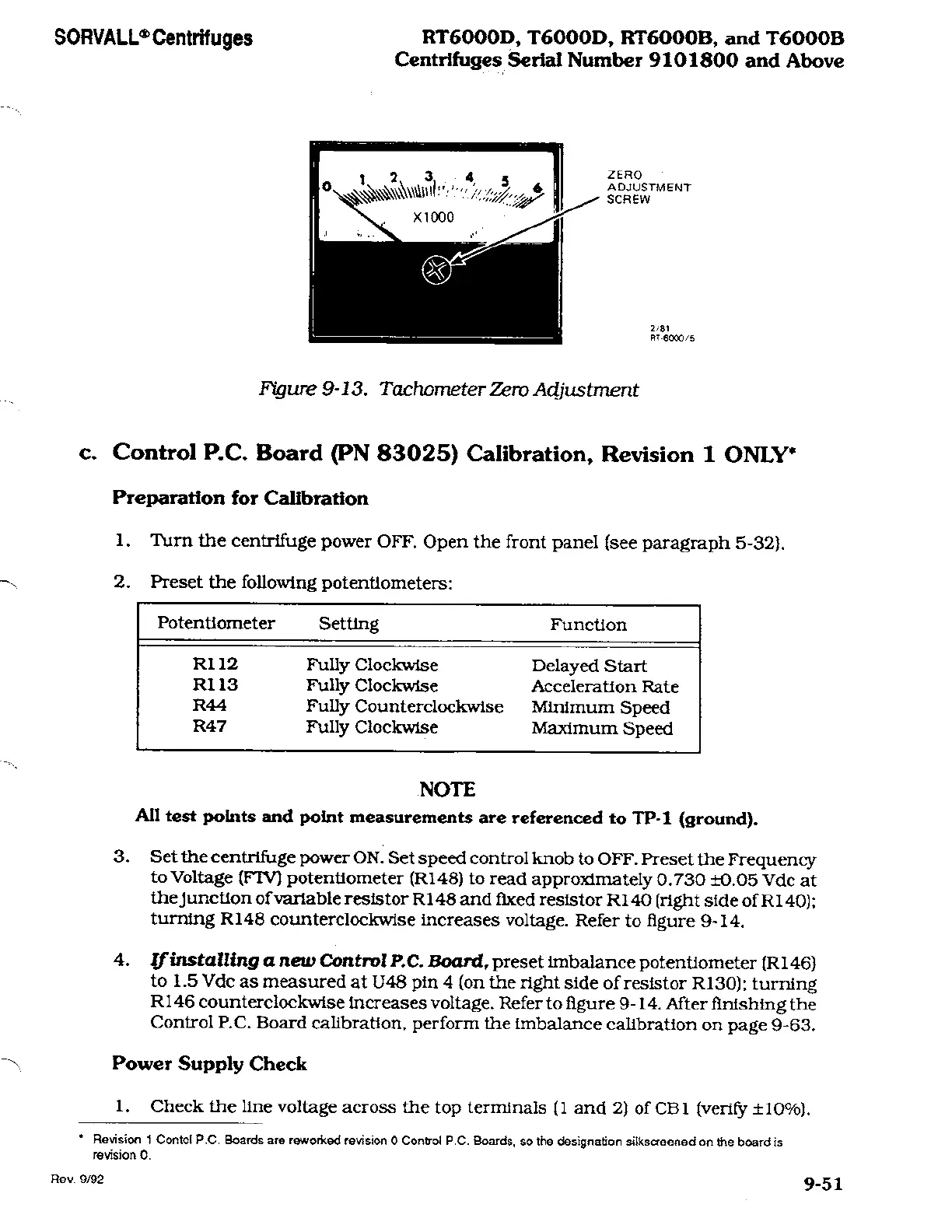
ZERO
ADJUSTMENT
SCREW
2/81
RT-6000/5
Figure
9-13.
Tachometer Zero Adjustment
c.
Control
P.C.
Board (PN
83025)
Calibration, Revision
1
ONLY*
Preparation
for
Calibration
1.
Turn
the
centrifuge
power
OFF.
Open
the
front
panel (see
paragraph
5-32).
2.
Preset
the
following
potentiometers:
Potentiometer
R112
R113
R44
R47
Setting
Fully
Clockwise
Fully
Clockwise
Fully
Counterclockwise
Fully
Clockwise
Function
Delayed
Start
Acceleration Rate
Minimum
Speed
Maximum
Speed
NOTE
All
test
points
and
point
measurements are referenced to
TP-1
(ground).
3.
Set the
centrifuge
power
ON.
Set
speed
control knob to
OFF.
Preset the
Frequency
to Voltage
(FTV)
potentiometer
(R148)
to read
approximately
0.730 ±0.05
Vdc
at
the
junction
of
variable
resistor
R148
and
fixed
resistor
R140
(right
side of
R
140);
turning
R148
counterclockwise increases
voltage.
Refer
to figure
9-14.
4.
If
installing
a new
Control
P.C.
Board, preset
imbalance
potentiometer
(Rl
46)
to 1.5
Vdc
as
measured at
U48
pin
4
(on
the
right
side
of
resistor
R130);
turning
R146
counterclockwise increases
voltage.
Refer
to figure
9-14. After finishing the
Control
P.C.
Board
calibration, perform
the imbalance calibration
on
page
9-63.
Power
Supply
Check
1.
Check the
line
voltage across
the
top
terminals
(1 and 2) of
CB1
(verify ±10%).
*
Revision 1
Contol
P.C.
Boards are reworked revision
0 Control
P.C.
Boards, so
the designation silkscreened
on
the board
is
revision
0.
Rev.
9/92
9-51
 Loading...