28
Master Section
1 - A1 - A
1 - A1 - A
1 - A
UX MASUX MAS
UX MASUX MAS
UX MAS
TERSTERS
TERSTERS
TERS
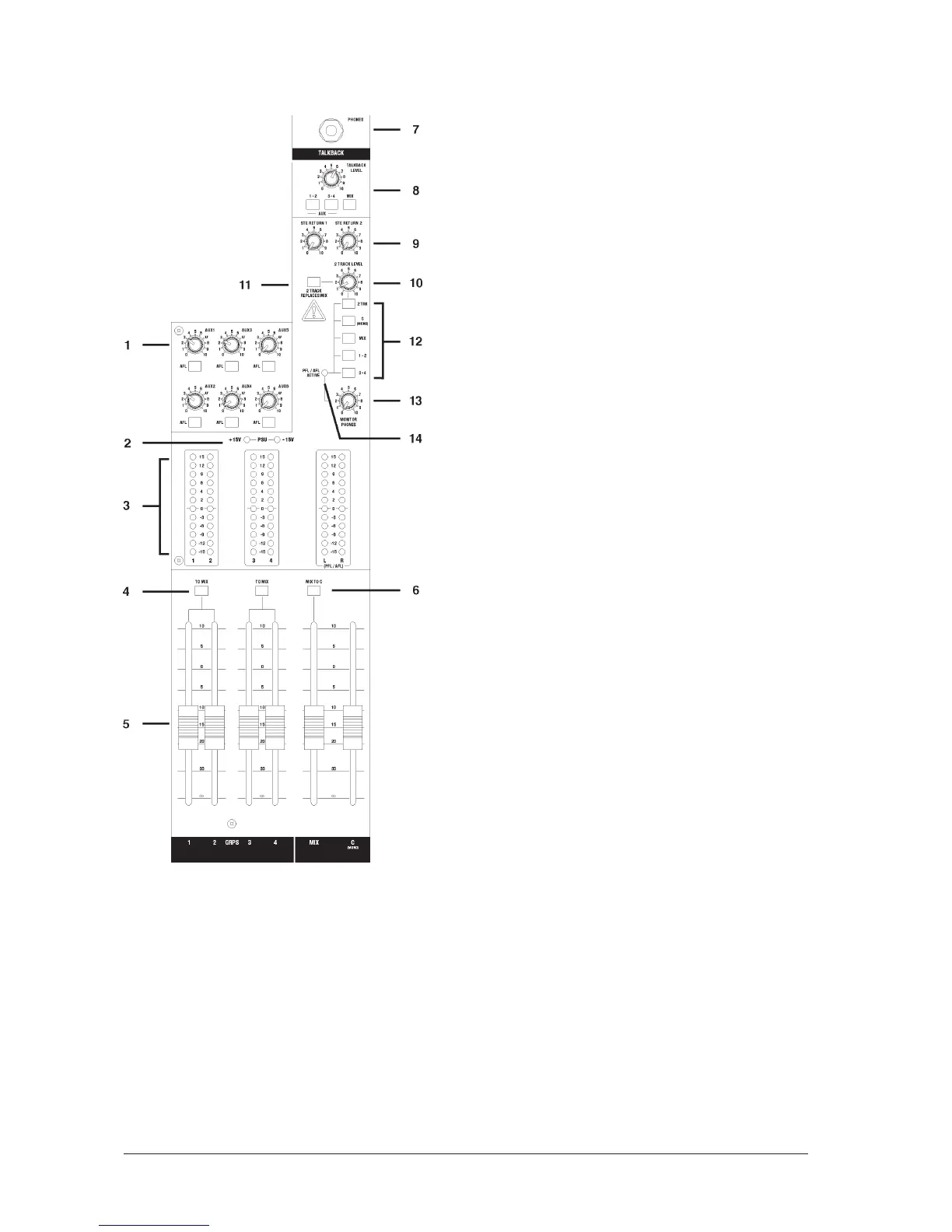
Each of the six AUX outputs has a master output level control and
associated AFL switch.
AA
AA
A
UX AFLsUX AFLs
UX AFLsUX AFLs
UX AFLs
Just as the Channel PFL switches allow pre-fade listening, so you can
monitor each AUX output after the level control by pressing the AFL
switch. This routes the AUX output signal to the MONITOR or PHONES,
replacing any existing signal which is selected. The METERS also switch
from the selected source to display the PFL/AFL signal and the PFL/
AFL LED lights to warn that a PFL or AFL switch is pressed. When you
release the switch the Monitor swaps back to the previous source.
2 - PO2 - PO
2 - PO2 - PO
2 - PO
WER INDICWER INDIC
WER INDICWER INDIC
WER INDIC
AA
AA
A
TT
TT
T
ORSORS
ORSORS
ORS
These LEDs light to show that power is connected to the console and
that the internal power supply is operating correctly.
3 - BAR3 - BAR
3 - BAR3 - BAR
3 - BAR
GRAPH METERSGRAPH METERS
GRAPH METERSGRAPH METERS
GRAPH METERS
3-colour peak reading BARGRAPH METERS are provided to monitor
the four Subgroup outputs and the selected Monitor + Phones source
(2TK, C (mono), Mix or Groups), giving you a constant warning of
excessive peaks in the signal which might cause overloading. Aim to
keep the signal within the amber segments at peak levels for best
performance.
Similarly, if the output level is too low and hardly registering at all on
the meters, the level of background noise may become significant.
Take care to set up the input levels for best performance.
When any PFL or AFL switch is pressed, the L & R meters automatically
switch to show the selected PFL/AFL signal on both meters, in mono.
4 - MIX4 - MIX
4 - MIX4 - MIX
4 - MIX
Pressing the Mix switch routes the post-fade Subgroup signals in pairs
to the main Mix. Groups 1 & 3 are routed to Mix L, Groups 2 & 4 are
routed to Mix R.
5 - MAS5 - MAS
5 - MAS5 - MAS
5 - MAS
TER FTER F
TER FTER F
TER F
ADERSADERS
ADERSADERS
ADERS
The MASTER FADERS set the final level of the Subgroup and Mix L & R
outputs. These should normally be set close to the `0’ mark if the
input GAIN settings have been correctly set, to give maximum travel on
the faders for smoothest control.
6 - MIX T6 - MIX T
6 - MIX T6 - MIX T
6 - MIX T
O C (mono)O C (mono)
O C (mono)O C (mono)
O C (mono)
Pressing this switch routes the post-fade Mix L/R outputs to the C
(mono) bus to create a separate mono mix to feed, for example, an
induction loop or centre cluster. Note: If there are input channels
which are routed both to Mix and C (mono), pressing this switch will
have an additive effect which may lead to feedback.
7 - PHONES7 - PHONES
7 - PHONES7 - PHONES
7 - PHONES
The PHONES output appears on a 3-pole 1/4” jack, suitable for
headphones with an impedance of 200Ω or higher.
 Loading...