Upper OLED Zone
A + sign indicated a
second function is
available by pressing
the encoder
Channel Name or ID see page 2-7
Displays LR_, __C, LRC or LCR depending on
channel type and routing/pan mode selected
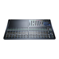
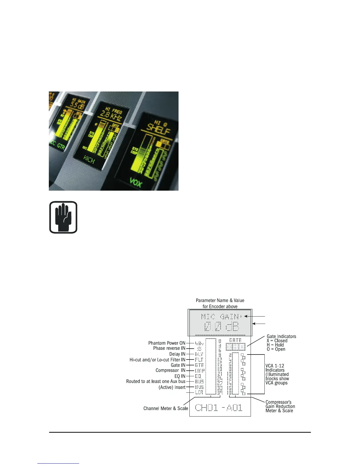
THE OLED DISPLAY
The OLED display (Organic LED) is central to the operation of the console and gives
you a lot of very useful information about the input channels and the encoders
located above them.
The OLED display is divided into three
sections with the top section (the
ORANGE part) always describing the
function of the encoder situated directly
above it.
The bottom section (the GREEN part)
gives the name of the channel located
below it.
Note! If you press the ‘i’ button the name of the physical connector that
the input channel is connected to will appear. This is very useful if you
have renamed your channels and need to nd out where the input is
derived from.
The area in the middle (the YELLOW part) gives information specic to the channel
below it. This includes metering for Input Levels, Noise Gate activity and Com-
pressor Gain Reduction. There are also status icons for VCA assignments and any
switches associated with the input channel (48v active, Phase active, EQ In etc.)
The OLED displays allow the user to see
at a glance exactly what is happening on
any of the input channels.
The diagram explains
what is displayed
on the OLED.
 Loading...