ETCPRSP01 0718
1.800.338.7337 / www.soundoffsignal.com
Pg. 3
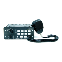
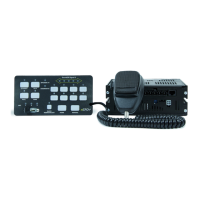
-Microphone Bracket Installation-
A metal clip is provided for mounting the microphone. Choose a
location convenient to the operator and away from any air bag
deployment areas. Using the mounting clip as a template, mark the
two holes to be drilled. Using a 1/8” drill bit, drill the two mounting
holes. Install the two #6 screws provided with the bracket.
WIRING:
WARNING! All customer supplied wires connecting to the
positive terminal of the battery must be sized to supply at least
125% of the maximum operating current and FUSED at the
battery to carry that load.
Ensure the amplier / relay unit is mounted in dry, protected
environment.
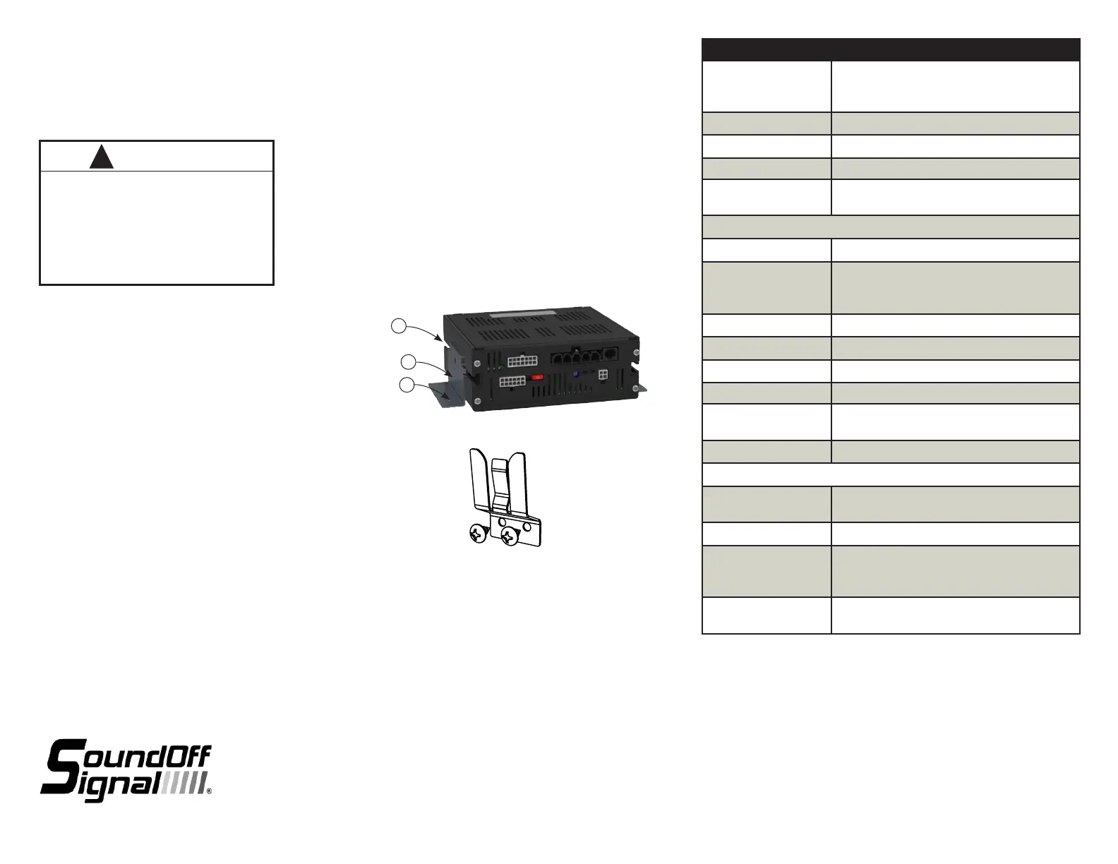
TECHNICAL SPECIFICATIONS
Overall Dimensions:
Control Panel:
Amplier/Relay:
3.51” W x 6.89”H x 1.17”D
2.62”H x 7.00”W x 6.51”D
Input Voltage: 10 - 16Vdc (negative ground)
Boxed Weight:
8 lbs.
Operating Temperature: -40°C to +50°C
Diagnostic LEDs: Speaker shorted/open, internal fuses open,
communications faults
Amplier
Input Current 7 Amps @ 13.4 VDC (100W Speaker)
Standby Current:
Ignition ON:
Ignition OFF:
500mA
<10mA
Output Power
:
ETSA481: 1x100W RMS Max (11 Ohm speaker)
Audio Frequency: 500-3 kHz
Siren Frequency: 675Hz - 1633Hz
High Voltage Protection: Limits to <18V*
Low Voltage Shutdown: Voltage<9.0V will cause siren output to cease
and will resume when system voltage is >9.5V
Speaker Protection: Shorted, Open: Stop output signal, preserve Amp
Light Control
AUX button relays: 9 total 10A max each circuit
Total current not to exceed 50A for CN8 pin 5
2 of the 9 available for external Arrow control
2 of the 9 have their source voltage switchable
from internal to external via fuse location, see
pg 5
Slide Switch Relays: 3 total 20A max each circuit,
Total current not to exceed 50A for CN8 pin 4
WARNING
!
Do not install this product or route its wires in
the air bag deployment area.
Doing so may cause damage to or reduce
effectiveness of the air bag, or create projectile
that could cause serious injury or death.
To determine air bag deployment area refer to
vehicle manufacturer's manual.
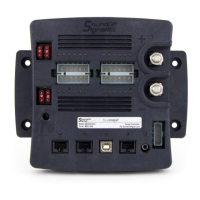
MOUNTING
-Amplier Installation-
Before drilling holes, check for clearance to prevent
damage. Check both sides of the mounting surface
before drilling and the be aware of any vehicle
components or other vital parts that may be damaged
during drilling.
Install grommets in any wire passage holes.
1. Slide ¼” hex head bolts into amplier t-slots.
2. Place mounting brackets over bolts.
3. Thread ¼” lock nuts onto bolts and tighten down.
4. Use mounting bracket holes to secure amplier
5. Install amplier with clearance from other objects
for improved ventilation.
1
2
4
400 SERIES AMPLIFIER BOX
PSRN4ANR1
 Loading...