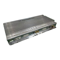
TOP
VlEW
FRONT VIEW BOTTOM
VlEW
8
l
6
1.
2.
3.
4.
5.
6.
)
8.
9.
10.
11.
12.
13.
KEY TO
CALLOUTS
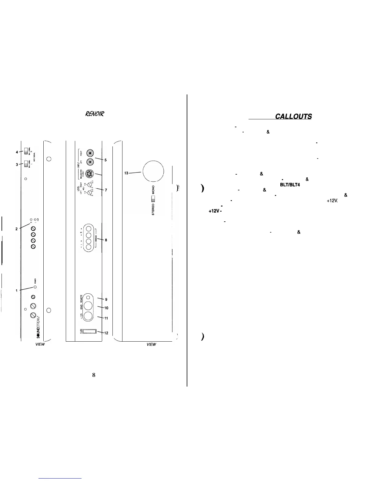
Power LED
-
Indicates amplifier power.
Clip Indicators
-
Channels 1
&
2; Indicates the signal output level is too high and
the output stage of the amplifier is clipping.
Left Channel Balanced/Unbalanced Input Selector
-
Channel 1; Select “BAL-
ANCED” to use the 6 pin Balanced signal input. Select “UNBALANCED” to use
the RCA signal inputs.
Right Channel Balanced/Unbalanced Input Selector
-
Channel 2; Select “BAL-
ANCED” to use the 6 pin Balanced signal input. Select “UNBALANCED” to use
the RCA signal inputs.
RCA Inputs
-
Channels 1
&
2; Right and Left channel RCA (Unbalanced) inputs.
Balanced Signal Input Connector
-
Channels 1
&
2; 6-Pin Balanced input con-
nector for use with the Soundstream
BLT/BLT4
Balanced Line Transmitter.
Input Levels
-
Channels 1
&
2; Independent Left and Right input level controls.
Speaker Connection Terminal
-
Speaker connections for Channels 1
&
2.
REMOTE
-
Remote turn-on input from the head unit. Accepts
+12V.
GND
-
Main ground connection. Bolt to a clean chassis point in the vehicle.
+12V
-
Connected to a fuse or circuit breaker, then to the battery’s positive termi-
nal
FUSE
-
Main power supply fuse. Warning: Replace only with the same value
fuse!
Stereo/Bridged Mono Switch
-
Channels 1
&
2; Select “Bridge” for bridged
mono operation (use right channel input). Select “Stereo” for two-channel op-
eration.