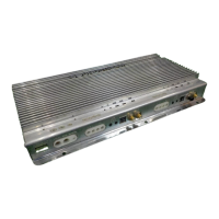
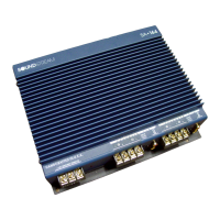
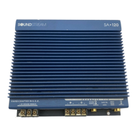
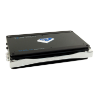
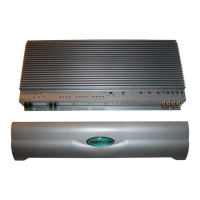
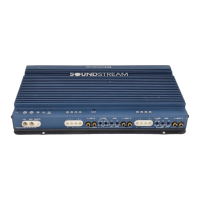
The Soundstream Stealth Series Amplifiers are high-efficiency Class D MOSFET amplifiers designed for mobile audio systems. They are engineered for versatility, offering compatibility with optional signal and audio processors, and are built with robust construction. The series includes several models: ST1.1000D, ST2.1000D, ST3.1000D, ST4.1200D, and ST5.1300D, each offering different channel configurations and power outputs.
Function Description
These amplifiers are capable of running a full-range system or can be selected to power only subwoofers. They feature quick-disconnect RCA and high-level wire harnesses, as well as quick-disconnect power and speaker output harnesses for easy installation. Top-mount crossover controls provide convenient access for adjustments after installation. A dash-mount subwoofer gain control module is included with some models for remote bass level adjustment.
Important Technical Specifications
Common Features Across Series:
- Amplifier Type: Premium High-Efficiency Class D MOSFET Amplifier.
- Chassis Design: Micro 3" x 8" (or 3" x 6" for ST2.1000D, 3" x 10" for ST5.1300D) chassis accommodates various applications.
- Heat Dissipation: Hybrid Aluminum Alloy Heatsink for optimum heat dissipation.
- Power Supply: MOSFET Power Supply with Audiophile Grade IRTM Transistors.
- PCB: Military Grade SMT PCB for dynamic performance.
- Protection Circuits: Direct Short, Thermal, & Overload Circuits protect the amplifier.
- Input Sensitivity: 500mV-12V Low-Level RCA or High-Level Signal Input (200mV-12V for ST5.1300D).
- Bass Boost: 0-18dB Variable 45Hz Bass Boost.
- Crossover Filters: Variable 12dB Low Pass and Subsonic Crossover Filters.
ST1.1000D (Monoblock Subwoofer Amplifier):
- Impedance Stability: 2-ohm Mono Minimum.
- Power Output:
- 350W x 1 @ 4-ohm Mono
- 500W x 1 @ 2-ohm Mono
- Crossover:
- 50-500Hz Variable Low Pass Crossover
- 10-50Hz Variable 12dB Subsonic Crossover
- Dimensions: 3"w x 1.50"h x 8"l
ST2.1000D (Two Channel Stereo Amplifier):
- Impedance Stability: 2-ohm Stereo & 4-ohm Bridged.
- Power Output:
- 140W x 2 @ 4-ohm Stereo
- 250W x 2 @ 2-ohm Stereo
- 500W x 1 @ 4-ohm Bridged
- Crossover:
- 50-500Hz Variable High Pass Crossover
- 50-500Hz Variable Low Pass Crossover
- Dimensions: 3"w x 1.50"h x 6"l
ST3.1000D (Three Channel Stereo Amplifier):
- Impedance Stability: 2-ohm Stereo & 4-ohm Bridged for speaker channel, 2-ohm Mono Minimum for subwoofer channel.
- Power Output:
- 65W x 2 @ 4-ohm Stereo + 200W x 1 @ 4-ohm Mono
- 100W x 2 @ 2-ohm Stereo + 300W x 1 @ 2-ohm Mono
- 200W x 1 @ 4-ohm Bridged + 300W x 1 @ 2-ohm Mono
- Crossover:
- 50-500Hz Variable High Pass Crossover (ch. 1 & 2)
- 50-500Hz Variable Low Pass Crossover (ch. 3)
- 10-50Hz Variable 12dB Subsonic Crossover (ch. 3)
- Dimensions: 3"w x 1.50"h x 8"l
ST4.1200D (Four Channel Stereo Amplifier):
- Impedance Stability: 2-ohm Stereo & 4-ohm Bridged.
- Power Output:
- 100W x 4 @ 4-ohm Stereo
- 150W x 4 @ 2-ohm Stereo
- 300W x 2 @ 4-ohm Bridged
- Crossover:
- 50-500Hz Variable High Pass Crossover
- 50-500Hz Variable Low Pass Crossover
- Dimensions: 3"w x 1.50"h x 8"l
ST5.1300D (Five Channel Stereo Amplifier):
- Impedance Stability: 2-ohm Stereo & 4-ohm Bridged.
- Power Output:
- 60W x 4 + 220W x 1 @ 4-ohm Stereo
- 90W x 4 + 300W x 1 @ 2-ohm Stereo
- Crossover:
- 50-500Hz Variable High Pass Crossover (ch.1-4)
- 50-500Hz Variable Low Pass Crossover (ch.5)
- 10-50Hz 12dB Subsonic Crossover (ch.5)
- Phase Shift: 0-180 Degree Phase Shift (ch.5)
- Dimensions: 3"w x 1.50"h x 10"l
Usage Features
- LINE IN (RCA): For source units with RCA line-level outputs, accepting levels up to 6Vrms (minimum 250mV required).
- High Level Input: Allows installation without connecting to the remote, but connecting the high-level ground wire to the head-unit ground is recommended for better sound quality.
- Thru-Out: Enables building multiple amplifier systems without splitter cords, by feeding the signal from one amplifier to the next via RCA jacks.
- Remote Bass Boost Control: Adjusts the bass boost gain for the amplifier.
- Speaker Connector: Specially tooled terminals designed to accommodate up to 18 gauge speaker wire.
- FUSE: Utilizes common automotive ATC type fuses; replace with the same value for continued protection.
- Power Input Connector: Main power input, must be connected directly to the positive (+) terminal of the car battery.
- Remote (Remote Input Connection): Turns on the amplifier by applying 12 volts, typically from the source unit's electric antenna or remote output. An 18 gauge wire is sufficient.
- GND (Ground Input Connection): Requires a good quality ground connection to the vehicle chassis for peak performance.
- Power Indicator: GREEN when power is on.
- Gain Adjustment Control: Adjusts the input level; turn clockwise if the car audio unit's output level seems low.
- Sub Sonic Filter: Variable (20Hz ~50Hz) to roll off unwanted frequencies below the set range, allowing wasted power to be used on audible bandwidth.
- Low Pass Filter: Internal variable filter, settable from 50Hz to 500Hz.
- Protection Indicator: Lights RED when activated. Refer to the Troubleshooting Guide.
- High Pass ON/OFF Selector Switch: When ON, the filter is set to High-pass via a potentiometer control.
- High Pass Filter: Internal variable filter, settable from 50Hz up to 500Hz, and some models up to 5KHz.
- High Pass/Full/Low Pass Selector Switch: Activated in each position in the top control.
- Remote Subwoofer Level Control: Allows control of the subwoofer output from the dashboard.
Maintenance Features
- Installation Precautions:
- Turn off all stereo and electrical devices before starting.
- Disconnect the negative (-) lead from the vehicle's battery.
- Ensure at least 2 inches (5 cm) clearance around air vents for proper cooling.
- Scrap away paint from ground points for bare metal contact.
- Use a utility knife to trim fabric from hole locations before drilling.
- Use grommets when running power cables through sheet metal to insulate metal edges from wire insulation.
- If possible, use tubing through grommets.
- Mounting: Choose a location allowing free air circulation (at least 2 inches/5 cm clearance on all sides). Protect from moisture and direct sunlight. Recommended locations: trunk floor, under driver's seat, or back of rear seat. Mounting feet are attached to the amplifier, used as a template for screw locations.
- Power Connections:
- Designed for 10-16.8 volt DC range. Check battery voltage before connecting.
- Wire directly to the vehicle battery with appropriate cable size.
- Use an inline fuse or circuit breaker as close to the battery positive (+) terminal as possible (no farther than 18 inches). The fuse value should not exceed the sum of the amplifier's internal fuses.
- Leave the fuse out or circuit breaker "off" until all other cable connections are made.
- Ground Connection: Locate a clean metal area close to the amplifier (e.g., floor pan). Remove paint, secure the ground cable with a bolt, star washer, and nut. Spread silicone over the connection to prevent rust and water leaks.
- Troubleshooting Guide: Provides solutions for common issues like power LED not ON, power LED GREEN with no output, protection LED ON, amplifier overheating, amplifier shutting down, low volume, alternator noise, and poor bass response.
- Internal Problem Indication: If the RED protection LED is activated with no speakers connected and all power connections are correct, it indicates an internal problem, requiring contact with Soundstream Technologies or a local dealer.
- Warranty: Limited 90-day consumer warranty. Extended two-year warranty with purchase and installation by a Soundstream authorized dealer. Warranty is void if the product is damaged by accident, unreasonable use, neglect, improper service, or other non-material/construction defects. Does not cover labor costs for removal/reinstallation. Requires proof of installation by an authorized dealer for the two-year warranty.