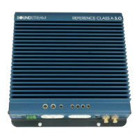
Do you have a question about the Soundstream Reference 414s and is the answer not in the manual?
Details on circuit board, power supply design, and thermal management.
Features like Class A stages, Drive Delay, and low impedance drive capabilities.
Covers input sensitivity, balanced/unbalanced inputs, and AIRBASS™ upgrade.
Smart Thermal Rollback™ and Fault Monitor LED functionality.
For identical left and right stereo channels, maximizing fidelity for satellite speakers.
For driving stereo and mono simultaneously, useful for center channels.
For dedicated single channel operation, ideal for subwoofers or high power needs.
Standard preamplifier outputs, no interface module needed.
Improved S/N ratio, excellent noise cancellation, immune to radiated noise.
Configuration guidance for RCA inputs, including noise troubleshooting.
Guidance for 6-pin DIN balanced input, including level settings.
Specifies gauge requirements for power and ground cables based on model and length.
Procedure to charge the capacitor bank without a spark using a resistor.
Requirement for fusing near the battery to prevent fire hazards.
Choosing a secure location with adequate ventilation for optimal operation.
Setting Coherent Stereo/Mixed-Mono/Bridged Mono and crossover switches.
Connecting audio, remote, power, and ground, followed by the power-up sequence.
Procedure for adjusting input levels for optimal output and balance.
Procedure for adjusting input levels, including sensitivity switch use.
Using clipping indicators and adjusting subwoofer level for balance.
Details on the on-board staggered electronic crossover for high and low pass filters.
Information on adding wireless remote control level adjustment for subwoofers.
Wiring diagram for 4 channels of full range output with RCA input.
Wiring for high pass satellite and RCA line out to subwoofer amplifier.
Wiring for high pass satellite and RCA line out to subwoofer amplifier.
Wiring for high pass satellites and bridged low pass subwoofer.
Wiring for bridged low pass satellites and RCA line out to satellite amp.
Wiring for bridged high pass satellites and RCA line out to subwoofer amp.
Identifies common issues like no sound, fault LED, and intermittent output.
Details circuits protecting against overheating and short circuits.
Key technical specifications including power, THD, and dimensions.
Illustrates series and parallel wiring configurations for speaker loads.
| Brand | Soundstream |
|---|---|
| Model | Reference 414s |
| Category | Amplifier |
| Language | English |
