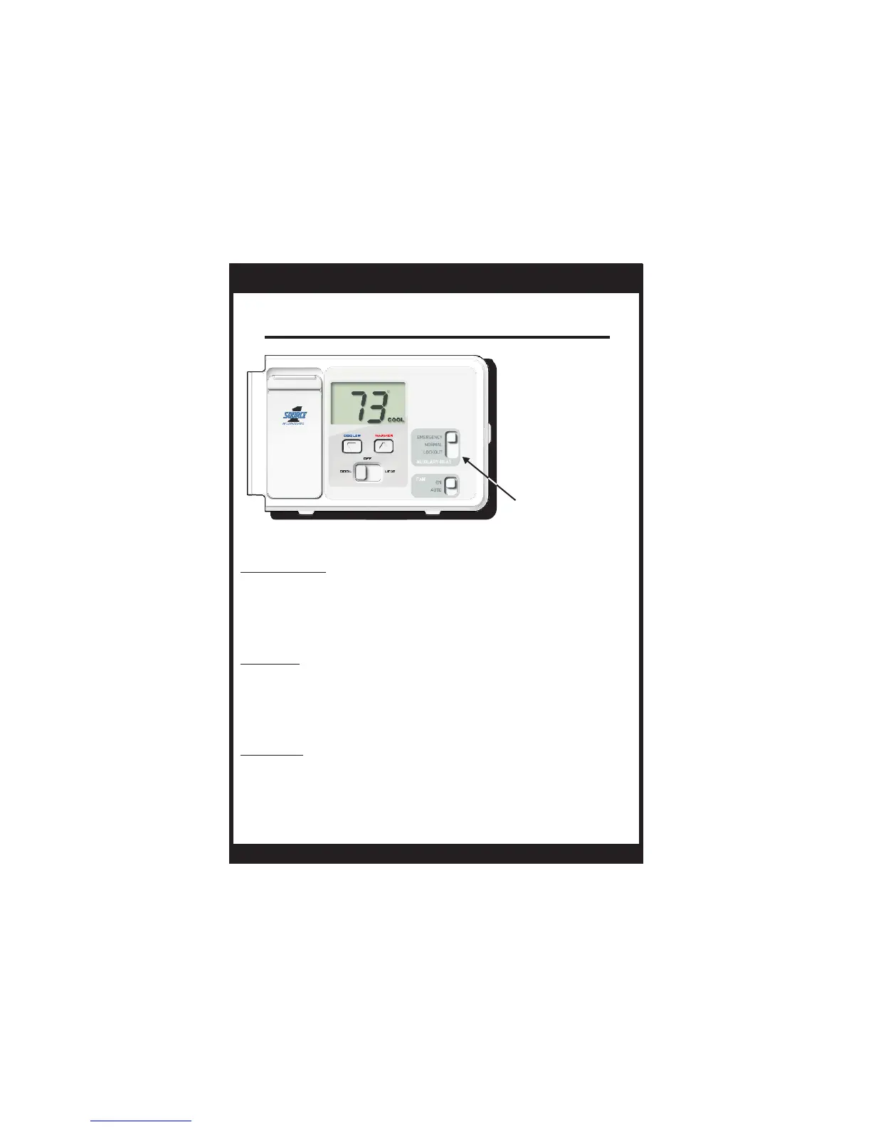
EasyManua.ls Logo

Source 1 S1-THEH21NS User Manual

Source 1 S1-THEH21NS
21 pages
To Next Page IconTo Next Page
To Previous Page IconTo Previous Page
Page #7 background imageLoading...
Page #7 background image
Page 7
AUX HEAT
SWITCH
Aux Heat
Normal - Aux Heat is allowed to run, if necessary,
along with the heat pump to satisfy the
heat demand.
Lockout - Aux Heat will never turn on
regardless of the heat demand.
OWNER'S MANUAL
S1-THEH21NS
When the Aux Heat switch is in the Emergency position the compressor will also be
locked out during cooling operation.
*
Emergency - Disables all compressor
functions* and energizes only Aux
Heat to satisfy the heat demand.
Question and Answer IconNeed help?

Do you have a question about the Source 1 S1-THEH21NS and is the answer not in the manual?

Source 1 S1-THEH21NS Specifications

General IconGeneral
BrandSource 1
ModelS1-THEH21NS
CategoryThermostat
LanguageEnglish

Summary

Safety Precautions and Guidelines

General Installation Safety

Disconnect power before servicing and follow all installation instructions carefully.

Battery Replacement Importance

Replace batteries annually or when 'Low Battery' icon appears for reliable operation.

FCC Compliance Information

Device operates under FCC rules, subject to conditions to prevent interference.

Front Panel Overview

Mode and Fan Control Switches

Controls system mode (Cool/Off/Heat) and fan operation (Auto/On).

Temperature Adjustment Controls

Allows user to adjust the desired temperature setting using buttons.

Auxiliary Heat Switch Function

Manages auxiliary heat mode: Emergency, Normal, or Lockout selection.

Thermostat Display Area

Shows current room temperature, set temperature, and system status indicators.

Understanding the Display Screen

Heat and Cool Status Indicators

Icons indicate heating or cooling is active; they flash when the system is energized.

Temperature Display Readings

Displays current room temperature and the desired set temperature.

Low Battery Warning Indicator

Alerts the user when battery power is low, indicating replacement is needed.

Auxiliary Heat Status Indicator

Indicates when the auxiliary heating system has been activated.

Normal Operation Guide

Mode and Fan Setting

Set Mode switch to Cool/Heat; Fan switch to Auto for typical operation.

Setting Desired Temperature

Use the Cooler/Warmer buttons to adjust the desired room temperature.

Auxiliary Heat Control Modes

Aux Heat: Emergency Mode

Disables compressor, uses only Aux Heat to satisfy heating demand.

Aux Heat: Normal Mode

Allows Aux Heat to run alongside the heat pump for heating demand.

Aux Heat: Lockout Mode

Prevents Auxiliary Heat from activating under any heating demand.

Temperature Unit Selection

Convert to Celsius

Press and hold Cooler/Warmer buttons simultaneously until Celsius is displayed.

Convert to Fahrenheit

Repeat the button press process to display temperature in Fahrenheit.

Installation Preparation Steps

Tools Needed for Installation

Flat Blade Screwdriver and Wire Cutter/Stripper are required for installation.

Initial Installation Checks

Ensure heat pump works, unpack carefully, and turn off power at the fuse panel.

Removing the Old Thermostat

Old Thermostat Cover Removal

Carefully remove the old thermostat cover, checking for screws if necessary.

Base Removal and Wire Labeling

Loosen base screws, disconnect wires, tape and label terminals for re-connection.

Keep Old Thermostat for Reference

Retain the old thermostat for comparison until the new unit is fully functional.

Battery Replacement Procedure

Accessing the Battery Compartment

Press down on the battery cover to open the slot and pull it out to access batteries.

Installing New Batteries

Remove old AA alkaline batteries and insert new ones into the compartment.

Securing the Battery Cover

Place the bottom hook of the battery cover into the slot and snap it closed.

Wire Connections and Terminals

Mapping Old to New Terminals

Match old thermostat terminals to new thermostat connectors using the provided chart.

Importance of Thermal Insulating Sheet

Do not remove the thermal insulating label to prevent wall drafts affecting readings.

Wiring Diagram: 4 Wire Heat Pump (O Reversing Valve)

System Type: 4 Wire Heat Pump

For residential heat pumps, split systems, package units with no auxiliary heat.

Connecting the Wiring

Connect thermostat wires to equipment based on terminal labels and diagram.

Optional Common Wire Use

Common wire is optional; if unused, thermostat is battery-powered.

Wiring Diagram: 5 Wire Heat Pump (O Reversing Valve)

System Type: 5 Wire Heat Pump

For residential heat pumps with auxiliary heat and 2 stages of heat.

Connecting the Wiring

Connect thermostat wires to equipment based on terminal labels and diagram.

Optional Common Wire Use

Common wire is optional; if unused, thermostat is battery-powered.

Wiring Diagram: 4 Wire Heat Pump (B Reversing Valve)

System Type: 4 Wire Heat Pump (B)

For residential heat pumps with B reversing valve, no auxiliary heat.

Connecting the Wiring

Connect thermostat wires to equipment based on terminal labels and diagram.

Optional Common Wire Use

Common wire is optional; if unused, thermostat is battery-powered.

Wiring Diagram: 5 Wire Heat Pump (B Reversing Valve)

System Type: 5 Wire Heat Pump (B)

For residential heat pumps with B reversing valve and auxiliary heat.

Connecting the Wiring

Connect thermostat wires to equipment based on terminal labels and diagram.

Optional Common Wire Use

Common wire is optional; if unused, thermostat is battery-powered.

Testing Heating Operation

Verify Heating System Activation

Set Mode to HEAT, adjust temp 10 deg above room, check HVAC unit energizes.

Test Auxiliary Heat Function

Set Aux Heat switch to NORMAL and verify Aux Heat icon appears.

Understanding Staged Heating

Details conditions for 1st and 2nd stage heating based on setpoint and deadbands.

Testing Cooling and Fan Operation

Verify Cooling System Activation

Set Mode to COOL, adjust temp 10 deg below room, check HVAC unit energizes.

Verify Fan Continuous Operation

Set Mode to OFF and Fan to ON to confirm continuous fan run.

Troubleshooting Common Issues

Stiff Slide Switch Remedy

If switches are stiff, loosen thermostat mounting screws slightly.

AC System Not Activating

Check setpoint, mode, batteries, and Aux Heat switch position for AC issues.

Fan Fails to Turn On

Ensure Fan Switch is firmly set to the On or Auto position for fan operation.

Troubleshooting System Faults

Auxiliary Heat Not Engaging

Verify Aux Heat Switch is set to Normal, not Lockout, for engagement.

Heating System Not Activating

Check heating setpoint, mode, batteries, and Aux Heat switch for heating issues.

One-Year Limited Warranty Details

Warranty Coverage Scope

Product is warranted against defects in material/workmanship for one year from installation.

Warranty Exclusions and Limitations

Excludes labor, installation, damage from misuse, voltage issues, or external factors.

Related product manuals