-4-
For Machines Mfd. Since 12/21
Model SB1007
INTRODUCTION
Untrained users have an increased risk of
seriously injuring themselves with this lathe.
Do not operate this lathe until you have
understood this entire manual and received
proper training.
Controls & Components
Refer to Figures 3–7 and the following
descriptions to become familiar with the basic
controls and components used to operate this
lathe.
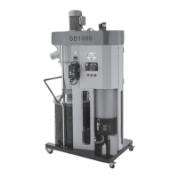
Headstock & Quick-Change
Gearbox
E. Quick-Change Gearbox Knobs: Control
leadscrew and feed rod speed for threading
and feed operations.
F. Thread and Feed Rate Charts: Display
position of quick-change gearbox knobs for
threading and power feed operations.
G. Jog Button: Rotates spindle forward while it
is pressed.
H. Stop Button: Stops all machine functions.
Twist clockwise to reset.
I. Feed Direction Lever: Selects carriage or
cross slide for power feed operations. The
spindle must be completely stopped before
using this control.
J. Spindle Speed Levers: Used in combination
to select any one of eight spindle speeds.
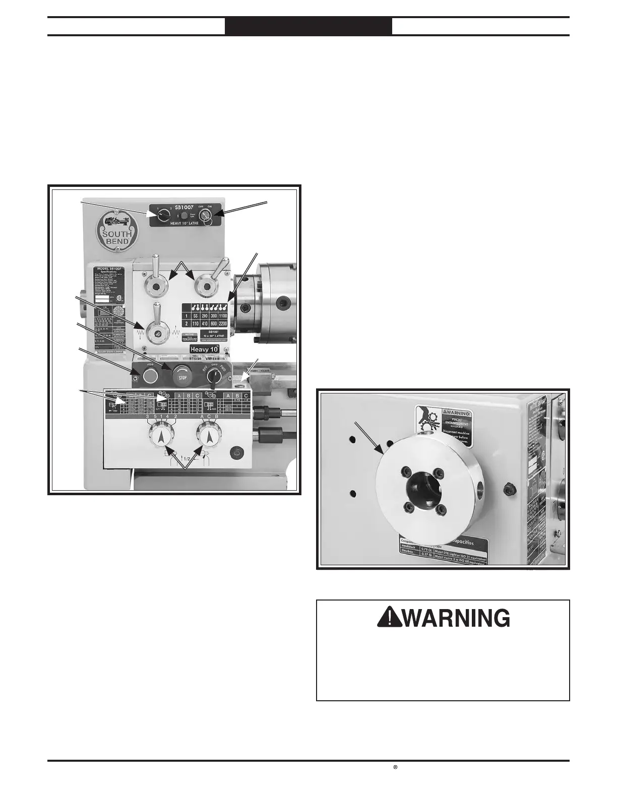
K. Spindle Spider: Provides support for long
workpieces that extend through the outboard
side of the spindle.
Figure Figure 3. Headstock and quick-change gearbox . Headstock and quick-change gearbox
controls.controls.
II
HH
GG
FF
AA
JJ
EE
DD
BB
CC
A. High/Low Range Switch: Determines spindle
speed within two speed ranges.
B. Master Power Switch: Regulates incoming
power to the lathe controls.
C. Spindle Speed Chart: Shows how to arrange
spindle speed levers for each of eight spindle
speeds.
D. Spindle Direction Switch: Selects forward
and reverse spindle rotation.
Figure Figure 4. Spindle spider components. Spindle spider components.
KK
 Loading...