V140701
P
W
R
E
R
R
02
/
24
14 : 49 : 04
FRI
Duty
:
0
P
W
R
E
R
R
02
24
14 : 49 : 04
FRI
Duty
:
0
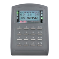
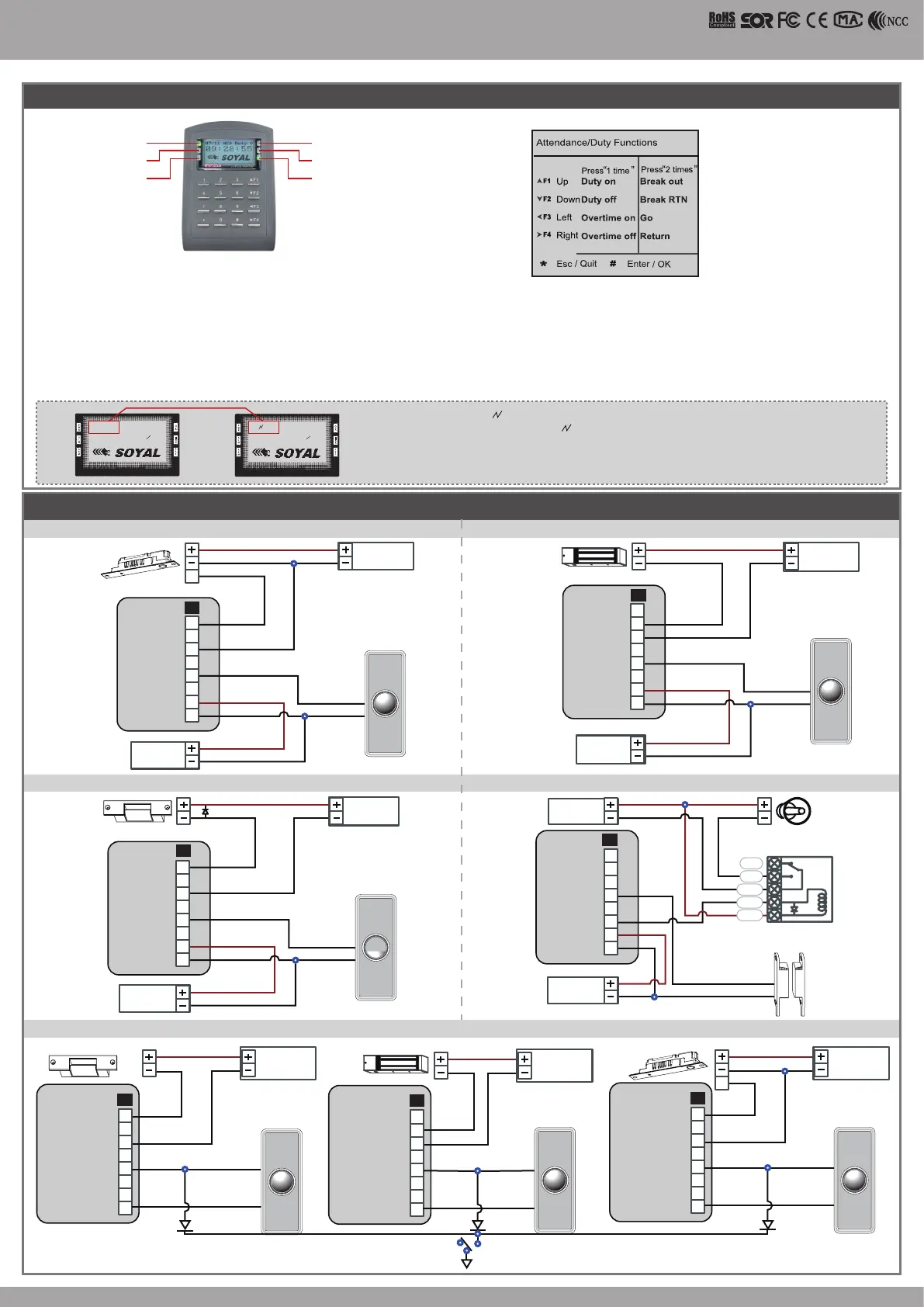
LCD Access Controller
Front Panel & Indicator
Connect to Electric Bolt
Wiring Diagram
EXIT
1
2
3
4
5
6
7
8
E
12V
GND
Exit Switch
12V
GND
12V
GND
N.O.
GND
N.O.
COM
PB
12V
GND
P1
Electric Bolt
Controller
RTE
POWER
12VDC
POWER
12VDC
EXIT
1
2
3
4
5
6
7
8
N.C.
COM
PB
12V
GND
12V
GND
12V
GND
12V
GND
N.O.
GND
P1
Controller
RTE
POWER
12VDC
POWER
12VDC
Magnet Lock
Connect to Magnet Lock
Connect to Electric Strike Connect to Door Contact
EXIT
1
2
3
4
5
6
7
8
12V
GND
12V
GND
12V
GND
N.O.
GND
N.O.
COM
PB
12V
GND
P1
Controller
RTE
POWER
12VDC
POWER
12VDC
Electric Strike
1. System will automatically exit from Programming Mode when inactivating for 30 seconds.
2. LED status indicates controller’s mode and status.
OK (green) – blinking constantly when operates in Programming Mode
– or ashing an existed card in card learn mode, it comes 2 beeps warning and LCD panel displays “Same Card: user address / card number”
Error (red) – invalid card with 2 beeps warning and LCD panel displays “Card Number Err!”
– or in anti-pass-back mode, when violates the access, it comes one beep warning and LCD panel displays “Anti-pass Error!”
Arming (green) – arming on status
Alarm (red) – any abnormal condition occurs
3. Keypad will be locked up 30 sec. when constantly entering incorrect pin code or master code.
4. Maximum error in[ut of pin code and master code can be changed via the software 701Server (default: 5 times)
Power
(Green)
Alarm
(Red)
Alarm
(Green)
OK
(Green)
Error
(Red)
In processing
(Green)
Networking : / and interactively ash between the Month and DAY.
[e.g.] 02/24←→02 24
Stand-alone : No ashing [e.g.] 02/24
(←Reference to picture)
If any re emergency, the people can escape by press a switch to open all doors
E
1
1
2
2
3
3
4
4
5
5
6
6
7
7
8
8
12V
GND
12V
GND
12V
GND
12V
GND
PB
PB
COM
COM
N.O.
N.O.
P1
P1
EXIT
1
2
3
4
5
6
7
8
12V
GND
12V
GND
PB
COM
N.C.
P1
EXIT EXIT
RTERTE
RTE
POWER
12VDC
POWER
12VDC
POWER
12VDC
Electric Strike
Electric Bolt
Fire Emergency
Transistor
IN4007
Transistor
IN4007
Magnet Lock
1
2
3
4
5
6
7
8
Door Contact
ALM
12V
GND
12V
GND
12V
GND
12V
GND
N.C.
P1
Controller
POWER
12VDC
POWER
12VDC
Alarm
Relay Outpot Module
Door Contact
N.C.
12V
N.O.
COM
CTL
 Loading...