SOYAL
ACCESS CONTROL SYSTEM
®
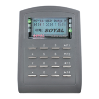
AR-727 (H-V5)
V140701
AR-821RB
P1 P2 P3
P4 P5 P6
3
1
2
5
4
Contents
2
User Guide
The communication wires and power line should NOT be bound in the same conduit or tubing.
Don’t equip reader and lock with the same power supply. The power for reader may be unstable when the lock is activating, that may make the
reader malfunction.
The standard installation: Door relay and lock use the same power supply, and reader use independent power supply.
Use AWG 22-24 Shielded Twist Pair to avoid star wiring ,CAT 5 cable for TCP/IP connection
1.Tubing:
2.Wire selection:
3.Power supply:
Installation
1
Products
3
Terminal Cables
4
Tools
5
Notice
Connector Table
◎
More details please go download by www.soyal.com
Optional
AR-721RB
Digital Relay
Wire Application Wire Color Description
Lock Relay 1 Blue White (N.O.)DC24V1Amp
2
Purple White
(N.C.)DC24V1Amp
Lock Relay COM 3 White (COM)DC24V1Amp
Door Contact 4 Orange Negative Trigger Input
Exit Switch 5 Purple Negative Trigger Input
Alarm Relay 6 Gray DC24V1Amp
Power 7 Thick Red DC 12V
8 Thick Black DC 0V
Cable: P1
Wire Application Wire Color Description
Beeper 1 Pink Beeper Output
5V/100mA, Low
LED
2 Yellow Red LED Output
5V/20mA, Max
3 Brown Green LED Output
5V/20mA, Max
Door Output 4 Blue White
Transistor Output Max. 12V/100mA
(Open Collector Active Low)
Wiegand
5 Thin Green Wiegand DAT: 0 Input
6 Thin Blue Wiegand DAT: 1 Input
WG Door
Contact
7 Orange Negative Trigger Input
WG Exit Switch 8 Purple Negative Trigger Input
P2
Wire Application Wire Color Description
1 --- ---
2 --- ---
TCP/IP Output 3
Orange White
Net - TX+
4 Orange
Net - TX-
5 Green White
Net - RX+
6 Green
Net - RX-
7 --- ---
P3
Wire
Application
Wire Color Description
RS-485 for Lift
Controller
1 Thick Green RS-485(B-)
2 Thick Blue RS-485(A+)
Cable: P4
Wire
Application
Wire Color Description
Anti-Tamper
Switch
1 Red N.C.
2 Orange COM
3 Yellow N.O.
P5
Wire Application Wire Color Description
Power 1 Red DC 12V
Output
Security trigger signal
2 Purple Security trigger signal Output
Arming 3 Red White Arming Output
Duress 4 Yellow White Duress Output
P6
Wire Application Wire Color Description
TTL Port 1 Black DC 0V
2 Yellow
TX
3 White
TE
4 Orange
RX
5 Red DC 5V
6 --- ---
Cable: CN11
(Optional:Lift Control w/ AR-725L485)
/ CN9
P7
Cable:
Cable:
Cable:
Cable:
Attach the water proof strip to the mounting plate.
Pull the cables from the square hole of the mounting plate.
Use a screwdriver to screw the base onto the wall.
Connect the terminal cables to the body and attach the body to the mounting plate.
Assemble the covers with the Allen key and screws (accessories supplied).
Turn on the power, the LED will light and hear the beep sound, you will see "Ready"" on LCD board.
Water proof Strip
6
5
4
3
2
1
P7
CN11
Optional Optional
Optional
6
5
4
3
2
1
P9
CN9
8
7
6
5
4
3
2
1
P2
CN5
321
P5
CN3
8
7
6
5
4
3
2
1
P1
CN4
2
1
P4
CN6
7
6
5
4
3
2
1
P3
CN7
4
3
2
1
P6
CN8
7
6
5
4
3
2
1
P8
CN18
Main PCB LCD-PCB
Wire Application Wire Color Description
HID RF Module 1 Orange
ANT 1
2
Purple
ANT 2
3 Black DC 0V
4 Red DC 5V
5 Blue Wiegand DAT: 1 Input
6 Green Wiegand DAT: 0 Input
7 White --
Cable: CN18
(Optional:HID ProxII RF Module)
P8
P9