– 9 –
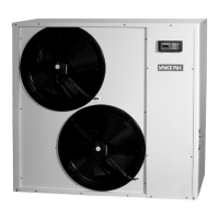
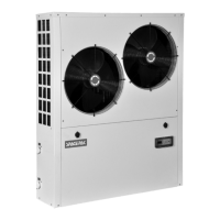
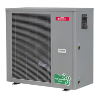
SIM Inverter Monobloc Air-to-Water Heat Pump
SECTION 2: INSTALLATION
Choose the Correct Heat Pump
Perform appropriate load calculation to determine required
heating or cooling load for the project. Refer to specifications in
this manual to determine proper size heat pump.
Installation Location
• SIM heat pump must be installed outdoors, in a location
capable of supporting the full weight, plus any potential snow
load. The outdoor unit must be secured to the support with
sufcient hardware to withstand any potential wind or seismic
conditions without shifting or tipping. Additionally, the outdoor
unit should be installed with enough clearance to allow for
condensate roll-off during the defrost cycle. This will prevent
freezing under the unit during defrost.
• The heat pump should be located away from sources of heat
or moisture such as combustion vents, dryer vents, building
exhausts, etc.
• Proper clearances shown on following page must be respected.
Water Loop Connection
Please read below for water piping instructions:
• The piping must be clean and free from dirt. Prior to insulating
the pipe, it is suggested that a leak test be performed to ensure
no water leaks are present.
• The system must be supplied with a pump sized to provide
the minimum ow rate specied in the Glycol/Water System
Design section of this manual. Pump selection must consider
the pressure loss through the plumbing system and its
components, plus the pressure loss through the heat pump’s
internal heat exchanger. The pump must be rated for the full
range of heated or chilled water temperatures, as well as any
anti-freeze or corrosion inhibitor additives.
• The piping system should have a wye strainer installed, on the
inlet side, that is sized properly for the anticipated ow rate
and pressure drop for the application. This will help protect
internal components of the heat pump against sediments,
contaminants and fouling that could damage the unit
• Do Not use the heat pump for DIRECT heating of potable
water. The heat exchanger and internal components are not
suitable for this application.
• Warning! Never expose the SIM Hydronic circuit to pressures
in excess of 30 PSI. Loss of coolant, property damage, or
equipment damage may result.
• The total system must be protected with a Pressure Relief
Valve or valves sized to protect the system component with
the lowest pressure rating. In no instance shall this exceed
30PSI.
• Caution! It is the responsibility of the installing contractor
to ensure that sufcient Propylene Glycol concentration is
maintained in the hydronic circuit to provide freeze protection
in all foreseeable conditions. Failure to do so voids the
warranty and damage caused by freezing is not covered.
Electrical Connections
SIM heat pump must be connected to an individual 230V
(220V-240V) circuit, sized and protected according to the
Minimum Circuit Ampacity and Max Overload Protection ratings
specied on the rating label afxed to the exterior of the unit.
The power connection must include a Protective Earth Ground
and a properly sized Neutral and two separate conductors in
accordance with National Electric Code and all local codes.
When using the SIM as a single standalone heat pump called
on by external inputs, (Thermostat, SSIC, Zoning controller etc.)
the low voltage wiring should be connected according to the
Field Wiring Diagram, to the terminals listed below.
Control Input connections
Important: All of the inputs are for voltage free relay contacts.
No voltage should ever be introduced to these inputs. Doing so
will immediately destroy the control and such damage will not be
covered under warranty.
Remote On/Off is a master unit enable. This must be closed for
all unit operation. This connection is located at the power input
side access panel.
Heat/Cool On/Off is the input for space conditioning. This must
be closed for operation in either Heating or Cooling mode. This
connection is located in the electrical compartment under the
top cover.
Remote Heat/Cool is the space conditioning mode selection.
Open results in Cooling operation, Closed results in Heating
operation. This connection is located at the power input side
access panel.
DHW On/Off enables the Domestic Hot Water mode. When
the contacts are closed, the SIM Control monitors the (potable)
Domestic Water temperature and automatically changes
over to maintain the DHW temperature according to the
parameters selected. This connection is located in the electrical
compartment under the top cover.
TT input is from a 10 thermistor sensor monitoring the DHW
Tank Temperature. This connection is located in the electrical
compartment under the top cover.
 Loading...