– 16 –
Model SCM Air to Water Heat Pump — Installation, Operation & Maintenance Manual
Section 8: Start-up and Test (continued)
Anti-freeze cycle
1. Should the water temperature drop to 34°F during periods
of non-use, the pump will start and the antifreeze heater (if
connected) will energize and continue to operate until the
temperature reaches 38°F.
2. If the water temperature continues to fall and reaches 33°F,
the Alarm symbol and Fault Code AL will be displayed,
and the unit will automatically start in heating mode. It will
continue to run until the water temperature reaches 38°F.
3. NOTE: This provides the maximum level of protection in all
cases, but may use energy unnecessarily when a suitable
concentration of glycol anti-freeze is installed. When freeze
protection is sufcient, these value can be adjusted to
lower temperatures. Contact technical support for guidance
in re-conguring these parameters, however it must be
understood that the installer is responsible for ensuring
sufcient freeze protection to the lowest temperature allowed.
24-Hour follow-up
Approximately 24 hours after start-up and testing, return to the
installation to verify proper operation. Perform the following
checks.
1. Check system pressure. Add additional glycol/water mixture
if needed to restore pressure. (Pressure can drop as air is
removed from the system by the air vents.)
2. Sample the glycol/water mixture in the system. Verify inhibitor
and glycol levels.
3. Inspect the piping and components to ensure there are no
leaks. Repair any leaks immediately.
4. Close the isolation valves on either side of the y-strainer at
the SpacePak heat pump return connection. Remove the
screen and inspect for sediment. Clean if necessary.
• If the strainer has become clogged with sediment, determine
whether the system needs to be drained, cleaned and re-
lled. Excessive sediment accumulation in the strainer will
reduce ow and cause the unit to shut down.
5. Cycle the system on heating and cooling. Verify that all
components operate correctly.
Electric Heat
The SCM series heat pumps are equipped with integral 3 kW
electric heater elements contained within the water circuit. These
are powered by a 230VAC input (separate from the heat pump
power) and must have individual protection, (minimum 15A)
The heater function is managed by the Carel μC2 controller, and
it provides three different functions, all of which are adjustable
via the Display Keypad.
A. Freeze protection: When the heat pump is in standby,
it monitors the temperature of the water circuit. If the
temperature falls below the value of parameter A04, the
controller will start the circulator, and send a call for the
heaters to energize. The heaters are powered through a Time
Delay Relay (TDR), to ensure ow is established before the
heaters come on. Parameter A05 is a differential value, such
that the heaters will shut off when the temperature reaches
A04 + A05.
B. Heat boost: When the heat pump is operating in heating
mode, the Carel controller will call for the heater to be
energized when the water temperature falls below the value
of parameter A08, again controlled by the TDR. Parameter
A09 is a differential value, such that the heaters will shut off
when the temperature reaches A08 + A09.
C. Defrost operation: When enabled, via parameter d11 being set
to a value of 01, the controller will call for the heater to energize,
after the TDR duration, whenever the defrost cycle is active.
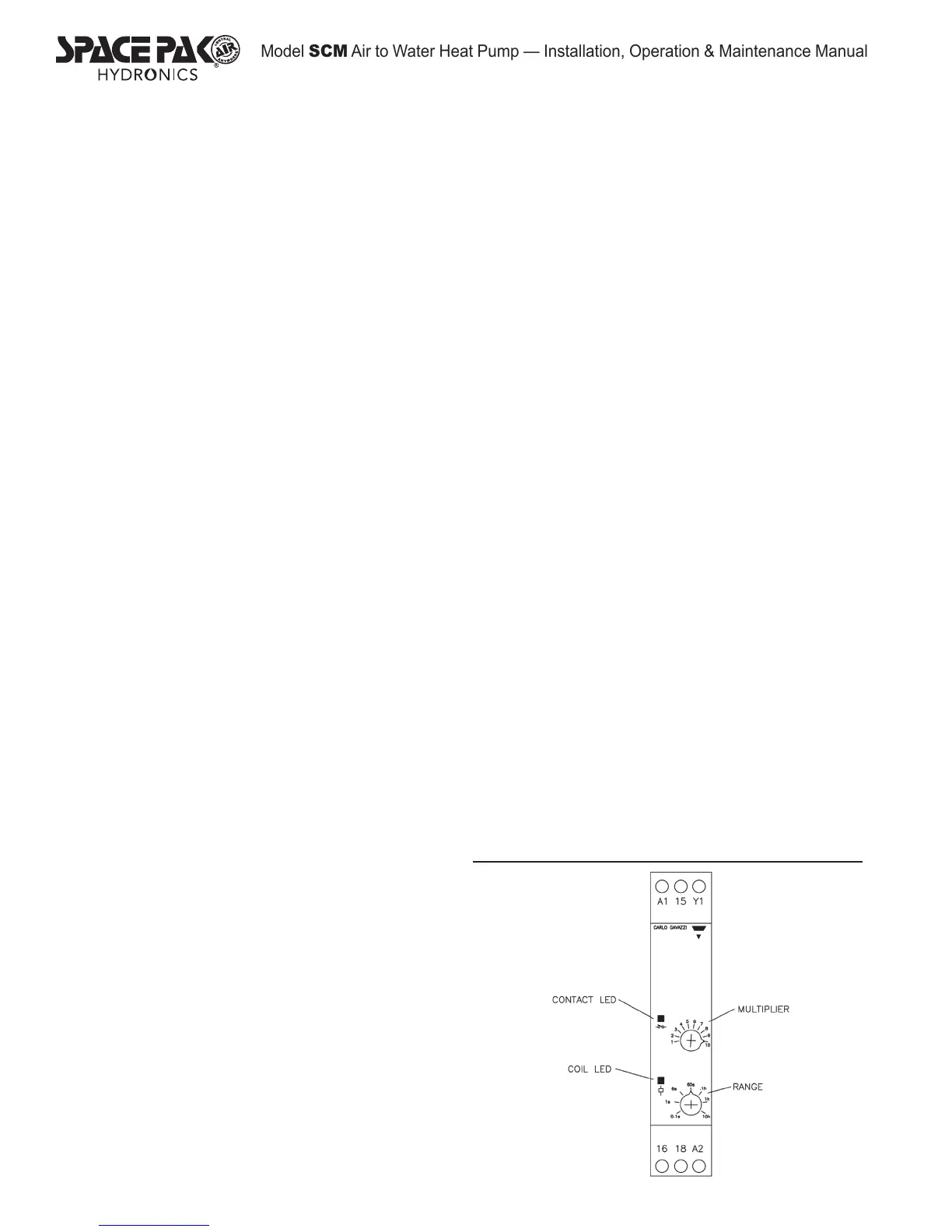
Time Delay Relay
In all instances, the heaters receive power only after a time
interval, controlled by the TDR. See Figure 15. The TDR can be
adjusted to provide a delay from .01 second, to 100 hours. This
is accomplished by two dials on the face of the components. The
lowed dial establishes the range, in increments of 0.1 second, 1
second, 6 seconds, 60 seconds, 0.1 hour, 1 hour, and 10 hours.
The upper dial is the multiplier, and increased the range from 1 to
10 times. The factory default is 10 minutes as shown in the gure;
the range is 60 seconds, and the multiplier is 10. This may be
excessively long for most applications, and may be adjusted to a
shorter interval, especially if it is primarily used for defrost operation.
When the TDR receives a signal from the controller, the Coil
LED will begin to ash, and continue for the duration of the time
delay. Once the delay has expired, the Coil LED will change to
solid, and the Contact LED will illuminate also. When the signal
is removed from the TDR, the contact will open immediately.
Protection
The heater circuit must rst prove water ow before energizing
the heaters, and maintain a circuit through an overtemp
protection device (located within the heater element) which
opens at 201°F. Should either of these conditions fail, the heaters
will immediately de-energize.
Heater Capacity
The internal circuit and switching is sufciently robust to carry the
load of the 3kW internal heater, or the (2) 3kW heaters within the
available BT-H series buffer tanks, but it cannot power all three
heaters. Therefore, the internal heater must be disconnected
from power when connecting buffer tank heaters.
Figure 15
 Loading...