EasyManua.ls Logo

Space Pak CSOLSTICE SIM-036 User Manual

Space Pak CSOLSTICE SIM-036
60 pages
To Next Page IconTo Next Page
Page #1 background imageLoading...
Page #1 background image
IAW2-0722
IN UNITED STATES: 260 NORTH ELM ST. WESTFIELD, MA 01085 800-465-8558 / FAX (413) 564-5815
IN CANADA: 7555 TRANMERE DRIVE, MISSISSAUGA, ONTARIO, L5S 1L4 (905) 670-5888 / FAX (905) 670-5782
SECTION 1: INTRODUCTION .......................................... 2
Hazard Denitions
Benets and Features
Specications
Performance
Typical System Diagram
SECTION 2: INSTALLATION ............................................ 9
Choose The Correct Heat Pump
Installation Location
Water Loop Connection
Electrical Connections
Control Input Connections
Control Output Connections
Dimensions
Required Clearances
SECTION 3: GLYCOL/WATER SYSTEM ......................... 13
SECTION 4: WIRING ........................................................ 15
Control Wiring Connection
Wiring Diagrams & Denitions
SECTION 5: REMOTE TOUCHSCREEN DISPLAY ........ 20
Overview of Remote Touchscreen Display
Electrical System Diagram
Display Windows and Functions
SECTION 6: PARAMETERS ............................................ 33
SECTION 7: TROUBLESHOOTING ................................. 49
SECTION 8: REPLACEMENT PARTS ............................. 51
WARRANTY ...................................................................... 57
MODEL SIM
INVERTER MONOBLOC
AIR-TO-WATER
HEAT PUMP
INSTALLATION AND
OPERATION MANUAL
Question and Answer IconNeed help?

Do you have a question about the Space Pak CSOLSTICE SIM-036 and is the answer not in the manual?

Space Pak CSOLSTICE SIM-036 Specifications

General IconGeneral
BrandSpace Pak
ModelCSOLSTICE SIM-036
CategoryHeat Pump
LanguageEnglish

Summary

SECTION 1: INTRODUCTION

Hazard Definitions

Defines safety terms like DANGER, WARNING, CAUTION, NOTICE used in the manual.

Benefits and Features

Highlights key advantages such as Inverter Compressor, Advanced Controls, and Easy Installation.

Specification

Cooling Specifications

Details capacity, efficiency, and temperature ranges for cooling mode operation.

Heating Specifications

Details capacity, efficiency, and temperature ranges for heating mode operation.

Electrical Specifications

Covers power requirements, fuse/breaker ratings, and motor data.

Refrigerant & Fan Specs

Lists refrigerant type, charge, and fan motor type and speed.

Sound & Hydronic Specs

Details noise levels and piping connection sizes.

Compressor & Dimensions

Provides compressor speed range and unit physical dimensions.

SIM-036 Performance Data

SIM-036 Heating Performance

Heating capacity and COP vs. ambient and water temperatures.

SIM-036 Cooling Performance

Cooling capacity and EER vs. ambient and water temperatures.

SIM-060 Performance Data

SIM-060 Heating Performance

Heating capacity and COP vs. ambient and water temperatures.

SIM-060 Cooling Performance

Cooling capacity and EER vs. ambient and water temperatures.

Typical System Diagram

SIM Heating with DHW Offset

Illustrates the system with domestic hot water integration.

SECTION 2: INSTALLATION

Choose the Correct Heat Pump

Guidance on selecting the appropriate heat pump model for the load.

Installation Location

Requirements and considerations for outdoor unit placement.

Water Loop Connection

Instructions for connecting the hydronic system piping.

Electrical Connections

Details on power supply and circuit requirements.

Control Input Connections

Wiring for external signals like On/Off and Heat/Cool.

Control Output Connections

Circulation Pump & Valve Control

Wiring for unit outputs like circulation pumps, 3-way valves, and DHW pumps.

Dimensions

SIM-036 Dimensions

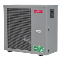
Physical size and layout of the SIM-036 unit.

SIM-060 Dimensions

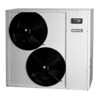
Physical size and layout of the SIM-060 unit.

Required Clearances

SECTION 3: GLYCOL/WATER SYSTEM

Glycol Concentration Guidelines

Recommends ethylene/propylene glycol ratios for operation based on ambient temp.

Glycol System Design Table

Provides capacity multipliers and pressure drop for glycol mixtures.

Glycol/Water System Design

System Volume & Expansion

Sizing requirements for circulating volume and expansion tanks.

Air Separator & Pressure Test

Procedures for air removal and system leak testing.

Insulate The Piping

Guidance on insulating pipes for cooling applications.

SECTION 4: WIRING

SIM Control Wiring Connection

How to connect external controls to the heat pump.

Internal Wiring Diagram - SIM-036

Field Connections Diagram - SIM-036

Internal Wiring Diagram - SIM-060

Field Connections Diagram - SIM-060

SECTION 5: REMOTE TOUCHSCREEN DISPLAY

Display Overview and Connection

Functionality and connection of the remote touchscreen.

Display Windows and Functions

Describes the main screen elements and user interactions.

Main Display Window

Display Window Contents & Buttons

Identifies key buttons like On/Off, Mode, Target Temp Set.

Main Display Animation

Explains visual indicators like defrosting icon and grey screen.

Mode Selection and Target Temperature Setting

Mode Selection Options

Explains how to choose between Hot Water, Heating, Cooling modes.

Target Temperature Setting

How to adjust setpoints for different operating modes.

Target Temperature Setting Screen

Lock Key Functionality

Timer Key

Timer Key Screen Operation

Interface for programming on/off times and days.

Settings Screen Overview

Settings > Status Menu

Displays real-time unit status, mode, and temperatures.

Settings > Electric Heating

Settings > Clock

Settings > Whisper Mode

Fast Whisper Function

Slows fans for quieter operation, reducing capacity.

Whisper Timer Function

Schedules quiet operation times for the unit.

Settings > Curve

Settings > Factory

Settings > Factory Passcode "22"

Parameters Submenu

Access to adjustable operational parameters.

Unit State Submenu

Load Status

Shows status of compressor, pumps, fans, and heaters.

Switch Status

Indicates state of protection switches and mode selectors.

Temp Status

Lists measured temperatures and pressures.

Settings > Factory > Passcode "22" > Failure

Failure Log Submenu

Access to view and clear fault history.

Settings > Factory > Passcode "22" > Brightness

Settings > Factory Passcode "66"

SECTION 6: PARAMETERS

Protection Parameters

Settings related to safety limits and freeze protection.

Defrost Parameters

Settings controlling the defrost cycle operation.

EEV Parameters

Settings for the Electronic Expansion Valve control.

Fan Parameters

System Parameters

Pump Parameters

Pump Operation Modes

Explains constant, on-call, and interval pump operation.

Pump Timing Settings

Details settings for pump run intervals and durations.

Temperature Parameters

Temperature Setpoints

Defines target temperatures for heating, cooling, and DHW.

High Temp Disinfection Settings

Parameters for sanitizing water via high temperature cycles.

Parameter A (Protection Parameters)

Anti-Freeze Protection Logic

How the unit detects and reacts to freezing conditions.

Malfunction & Recovery Behavior

Unit response to faults and recovery procedures.

Parameter D (Defrost Parameters)

Defrost Entry Requirements

Conditions that trigger the defrost cycle.

Defrost Stop Requirements

Conditions that terminate the defrost cycle.

Defrosting Action Sequence

Step-by-step process during defrost operation.

Abnormal Defrost Handling

How the unit manages unexpected defrost terminations.

Parameter F (Fan Parameters)

Fast Mute Function

How to enable and use the fast fan silencing feature.

Timing Mute Function

How to schedule quiet fan operation times.

Parameter H (System Parameters)

Parameter P (Pump Parameters)

Pump Operation Modes

Explains constant, on-call, and interval pump operation.

Pump Timing Settings

Details settings for pump run intervals and durations.

Parameter R (Temperature Parameters)

Compressor Short Cycle Protection

Prevents rapid compressor cycling to ensure longevity.

ModBus BMS Controls

How to integrate the unit with building automation systems.

Modbus RTU Protocol Details

SIM Error Codes

Start-up Errors

Codes related to the unit failing to start.

Sensor Faults

Codes indicating sensor failures (temp, pressure).

Pressure Faults

Codes for high/low pressure issues and flow errors.

Protection Faults

Codes for freeze, overheat, voltage, and current protection trips.

Communication & Other Faults

Codes for communication errors and other system faults.

SECTION 7: TROUBLESHOOTING

Sensor & Pressure Faults

Addresses issues with temperature sensors, pressure switches, and pressure readings.

System Protection Faults

Troubleshooting for freeze, overheat, voltage, and current protection errors.

Communication & Control Faults

Resolving issues with communication boards and control logic.

Compressor & Fan Faults

Diagnosing problems related to compressor or fan operation.

Input Voltage & Power Issues

Troubleshooting power supply and voltage-related faults.

Troubleshooting Specific Failures

Unit Cannot Be Started

Solutions for issues preventing unit startup.

Low Capacity or Compressor Not Stopping

Addresses performance issues and compressor control problems.

High Compressor Exhaust & System Pressure Issues

Diagnosing high exhaust and system pressure problems.

Fan & Water Flow Issues

Troubleshooting fan operation and low water flow conditions.

Compressor Not Running or Low Capacity

Solutions for compressor not running or low heating/cooling output.

Low Outlet Water Temp & Low Water Flow

Addresses issues with outlet water temperature and water flow protection.

SECTION 8: REPLACEMENT PARTS

SIM036 Parts Identification

Diagram showing numbered components for SIM036.

SIM060 Parts Identification

Limited Warranty Statement

Solstice Inverter Series Warranty

Details warranty periods for parts and compressor for inverter models.

Air Handler & Fan Coil Warranty

Warranty terms for related accessories.

SpacePak Buffer Tanks Warranty

Warranty Terms & Conditions

Covers labor exclusions, installation requirements, and service procedures.

Warranty Exclusions

Lists conditions not covered by the warranty, like misuse or improper installation.

Related product manuals