– 34 –
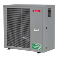
SIM Inverter Monobloc Air-to-Water Heat Pump
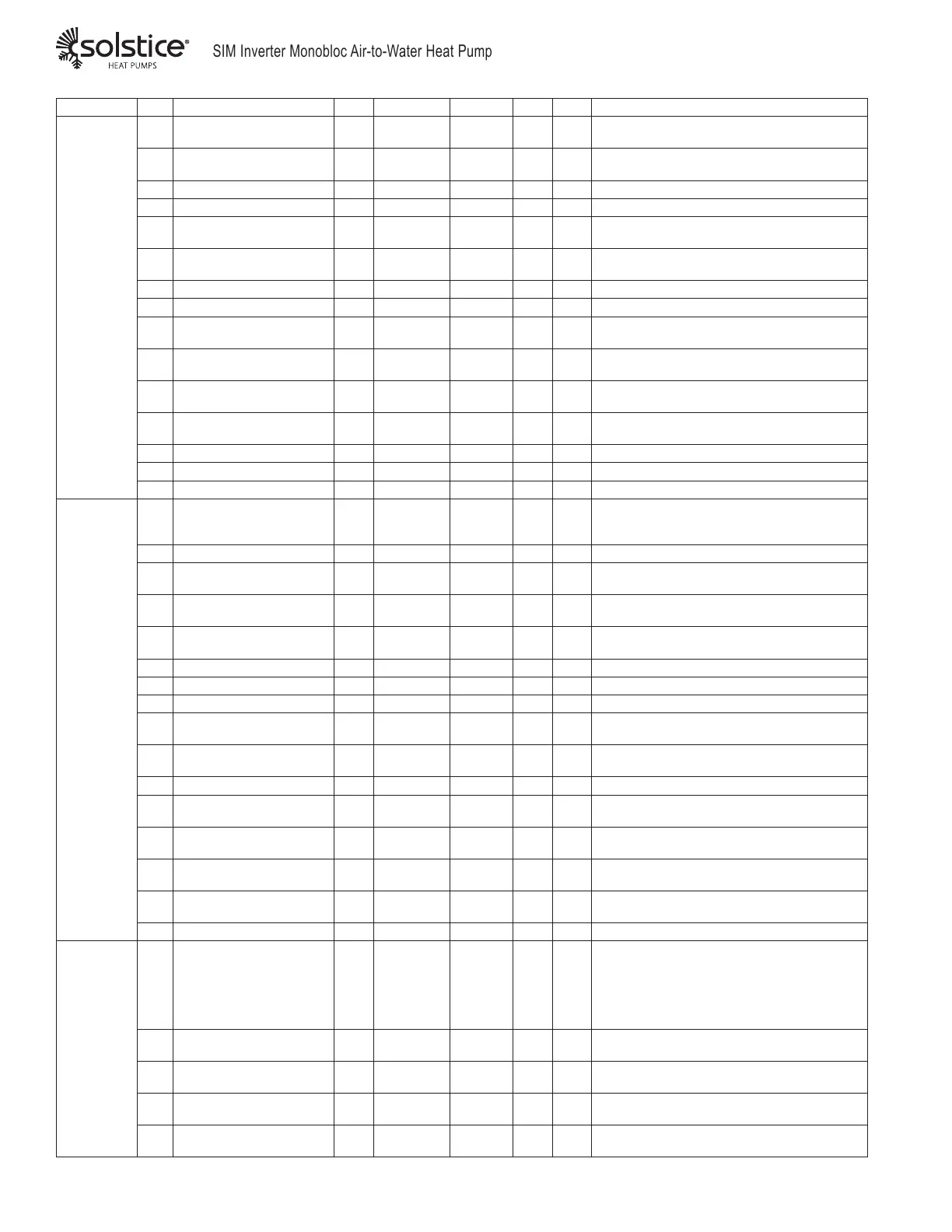
Top Menu Code Description Units Range Passcode -036 -060 Notes
Fan
F01 Max Fan Speed in Heating RPM 0 to 2000 66 850 850
Max value at minimum suction pressure. Do not
exceed
F02 Min Fan Speed in Heating RPM 0 to 2000 66 300 300
Main value at maximum ambient temperature.
Do not set lower
F03 LP of Suction for Heating PSI 0 to 290 66 58 58 Minimum Suction Pressure for Max Fan Speed
F04 HP of Suction for Heating PSI 0 to 290 66 160 160 Maximum Suction Pressure for Min Fan Speed
F05 Max Fan Speed in Cooling RPM 0 to 2000 66 850 850
Max value at maximum suction pressure. Do not
exceed
F06 Min Fan Speed in Cooling Deg F 0 to 2000 66 300 300
Main value at minimum ambient temperature. Do
not set lower
F07 HP of Exhaust in Cooling PSI 0 to 725 66 377 377 Maximum Discharge Pressure for Max Fan Speed
F08 LP of Exhaust in Cooling PSI 0 to 725 66 290 290 Minimum Discharge Pressure for Min Fan Speed
F09 Manual Fan Speed RPM 0 to 1000 22 0 0
Manual override at xed speed. If value is 0, fan
speed is automatic
F10 Timer Mute - 0 ~ 1 66 0 0
Silent mode enabled if value is 1, not enabled if
value is 0
F11 Mute Timer Start Hour Hr 0 to 23 66 0 0
Time of day (whole hour, 24 hr clock) to start
Silent Mode
F12 Mute Timer End Hour Hr 1 to 23 66 0 0
Time of day (whole hour, 24 hr clock) to end
Silent Mode
F13 Mute Mode Speed RPM 300 to 1300 66 600 600 Max allowed fan speed during Silent Mode
F14 DC/EC Fan Rated Speed RPM 0 to 1300 66 600 600 Manufacturer setting, do not alter
F15 Fan Motor Type - 0 to 2 66 1 2 Quantity of Fans
System
H01 Auto Start - 0~1 66 1 1
If value is one, unit will retain On/
Off status after power reset.*
*Signicant only in "Master mode"
H02 Master/Member Unit - 0/1 22 0 0 0 = Touchscreen operation, 1 = Wired operation
H03 Temperature Units - 0~1 66 1 1
0 = Temps displayed in °C, press.in Bar, 1=
Temps in °F, press. in PSI
H04 4-way valve polarity - 0~1 66 0 0
0= Reversing Valve de-energized in heating,
1=RV energized in Heating
H05 3-way valve polarity - 0~1 22 1 1
0=3-way valve de-energized in DHW, 1=3-way
valve energized in DHW
H06 EEV Control P Value - 1 to 100 66 5 5 Manufacturer setting, do not alter
H07 EEV Control I Value - 1 to 100 66 3 3 Manufacturer setting, do not alter
H08 EEV Control D Value - 0 to 100 66 0 0 Manufacturer setting, do not alter
H09 Min Frequency Hz 20 to 60 66 30 30
Minimum compressor drive frequency limit at low
load
H10 Max Frequency Hz 30 to 120 66 1 1
Maximum compressor drive frequency limit at
high load
H11 Model Selection - 0 TO 50 66 17 17 Set specic to Compressor Type, do not alter
H12 Hand Drive Frequency Hz 0 to 90 66 0 0
Manual compressor frequency override.
0=Automatic modulation
H13 PFC Function Enabled - 0~1 66 1 1
1=Power Factor Correction feature is enabled.
0=Disabled
H15 Unit Address - 1 to 99 66 1 1
Unique network address if units are connected
together via RS485
H16
Heating/Cooing and Hot
Water Function
- 0~1 66 0 0 0=DHW Mode Disabled, 1=DHW Mode Enabled
H17 Cooling Mode - 0~1 66 1 1 0=Cooling Mode disabled, 1=Cooling Mode available
Pump
P01 Pump Operation - 0 to 2 22 0 0
P01=0-CONSTANT, pump runs whenever the
unit is active in heating or cooling operation
1-ON CALL, pump runs when the unit is active
and the compressor is running
2-INTERVAL, pump runs for short pulses to
sample system water temperature.
P02 Interval Pump Off duration Min. 1 to 120 22 10 10
P02= RUNNING INTERVAL TIME between starts
during Interval operation
P03 Interval Pump On duration Min. 1 to 30 22 3 3
P03= RUNNING DURATION during interval
operation.
P04 Advanced Start Time Min. 0 to 30 22 1 1
P04= ADVANCE START TIME, in minutes,
between Pump Start and Compressor Start
P05 Manual Control - 0~1 22 0 0
P05= NO, MANUAL CONTROL Feature is not
available in this model. Do not change.