– 5 –
Model SCM Air to Water Heat Pump — Installation, Operation & Maintenance Manual
Section 2: SCM Field Adjustable Parameters (continued)
SCM Controller
The SCM controller allows the adjustment of heating & cooling setpoints, differentials, and defrosting parameters.
The following chart depicts the factory default values for the most commonly adjusted parameters.
Certain read only parameters are available to evaluate performance or troubleshoot faults. These are accessed through the same
parameter menu and are listed below.
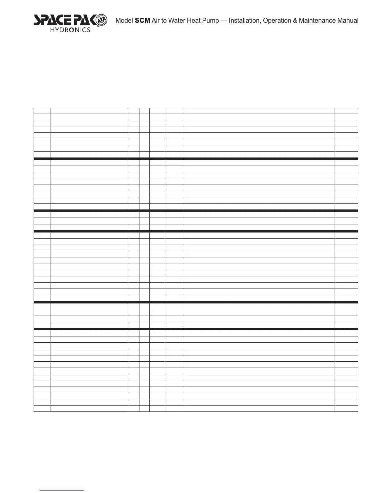
DISPLAY DESCRIPTION MIN MAX UOM DEFAULT MEANING PASSWORD
A01 Low Temp Alarm A07 A04 °F 34.0 Water temperature below which the Low Temp alarm A1 will activate 22
A02 Alarm differential 0.3 122.0 °F 4.0 Alarm A1 turns off at A01 + A02 22
A04 Aux heater setpoint A01 r16 °F 36.0 Water temperature below which the pump and electric heater, if present, engage.
A05 Differential for aux heater 0.3 50.0 °F 5.0 Pump and heater turns off at A04+A05 22
A07 Antifreeze alarm set point limit -40.0 176.0 °F 32.0 Minimum temperature that A01 can be set to 66
A08 Auxiliary heater set point in heating mode A01 r15 °F 90.0 Water temperature below which the electric heater, if present, engages in heating mode 22
A09 Auxiliary heater differential in heating mode 0.3 50.0 °F 5.0 Electric heater turns off at A08 + A09 in heating. 22
b00 Default display value 0 10 Flag 0 b00 = 0 Displays return water temperature b00 = 01 displays supply water temperature 22
b01 Probe B1 reading - - °F - Read only, real time return water temperature 00
b02 Probe B2 reading - - °F - Read only, real time sys 1 HX leaving water temp 00
b03 Probe B3 reading - - °F - Read only, real time Sys 1 OS coil surface temperature 00
b04 Probe B4 reading - - °F - Read only, real time ambient air temperature 00
b05 Probe B5 reading °F - Read only, real time supply water temperature 00
b06 Probe B6 reading °F - Read only, real time sys 2 HX leaving water temp 00
b07 Probe B7 reading - - °F - Read only, real time Sys 2 OS coil surface temperature 00
c10 Accumulated compressor #1 hours (System 1) - - hrs x 100 - Value x 100 is the accumulated compressor run time in hours 00
c12 Accumulated compressor #3 hours (System 2) hrs x 100 - Value x 100 is the accumulated compressor run time in hours 01
C15 Accumulated pump hours - - hrs x 100 - Value x 100 is the accumulated pump run time in hours 00
d01 Defrost cycle 0 1 Flag 0 Defrost feature currently disabled 22
d02 Defrost logic 0 2 Flag 0 Defrost on timed cycle 22
d03 Start defrosting temperature 0.0 d04 Bar 3.2 Coil temperature below which Defrost initiates 22
d04 End defrosting temperature 0.0 176.0 °F 45 End defrost temperature 22
d06 Min. duration of a defrosting cycle 0 150 Second 60 Minimum defrost duration even if all conditions are satised. 22
d07 Duration of a defrosting cycle 1 150 Minute 5 Time duration of a defrost cycle for one system. 22
d08 Time between defrost cycle 10 150 Minute 45 Run time between defrost cycle starts in one system 22
d09 Delay between two circuits 0 150 Minute 10 Minimum delay between start of defrost of one cuircuit to start of defrost of other circuit 22
d11 Immersion heaters on during defrost 0 1 Flag 1 Turns on electric immersion heater to offset heat loss during defrost cycle. 22
d16 Forced ventilation time at the end of the defrosting 0 360 Second 45 Duration of fan operation at full speed to clear water from coil 66
d17 Defrost with compressors OFF 0 80.0 °F 55.0 Temperature above which defrost occurs with fans only. 66
F02 Fan operating logic 0 2 Flag 1
0=Fans on whenever unit is on, 1=both fans on when either compressor is running,
2=both fans on when either compressor is running and coil temp is above threshold
66
F05 Temperature for fans off in cooling -40.0 °F 75.0 Coil temperature below which fans turn off (if F02=2) (See Fig 1) 22
F06 Temperature differential to turn fans back on 0.0 50.0 °F 10.0 Fans turn back on at F05+F06 (if F02=2) (See Fig 1) 22
r01 Cooling set point r13 r14 °F 42.0 Primary cooling setpoint (See Fig 3) 00
r02 Cooling differential 0.3 50.0 °F 8.0 Cooling differential/hysteresis 00
r03 Heating set point r15 r16 °F 120.0 Primary heating setpoint (See Fig 5) 00
r04 Heating differential 0.3 50.0 °F 8.0 Heating differential/hysteresis 00
r13 Min. Cooling set point -40.0 r14 °F 36.0 Minimum allowable cooling setpoint 22
r14 Max. Cooling set point r13 176.0 °F 60.0 Maximum allowable cooling setpoint 22
r15 Min. Heating set point -40 -40.0 °F 55.0 Minimum allowable Heating setpoint 22
r16 Max. Heating set point r15 176.0 °F 125.0 Maximum allowable Heating setpoint 22
r17 Cooling compensation constant -5.0 +5.0 °F 0.0 Slope of Outdoor reset curve, Deg water temp/Deg ambient temp. Cooling mode (See Fig 5) 22
r18 Maximum distance from the set point 0.3 20.0 °F 8.0 Maximum deviation from setpoint that can be achieved by outdoor reset (See Fig 5 & Fig 6) 22
r19 Start compensation temperature in cooling mode -40.0 176.0 °F 85.0 Ambient air temp above which Outdoor Reset is active in Cooling (See Fig 5) 22
r20 Start compensation temperature in heating mode -40.0 176.0 °F 30.0 Ambient air temp below which Outdoor Reset is active in Heating (See Fig 6) 22
r31 Heating compensation constant -5.0 +5.0 °F 0.0 Slope of Outdoor reset curve, Deg water temp/Deg ambient temp. Heating mode (See Fig 6) 22


 To Next Page