98
0700-M001-0-P1
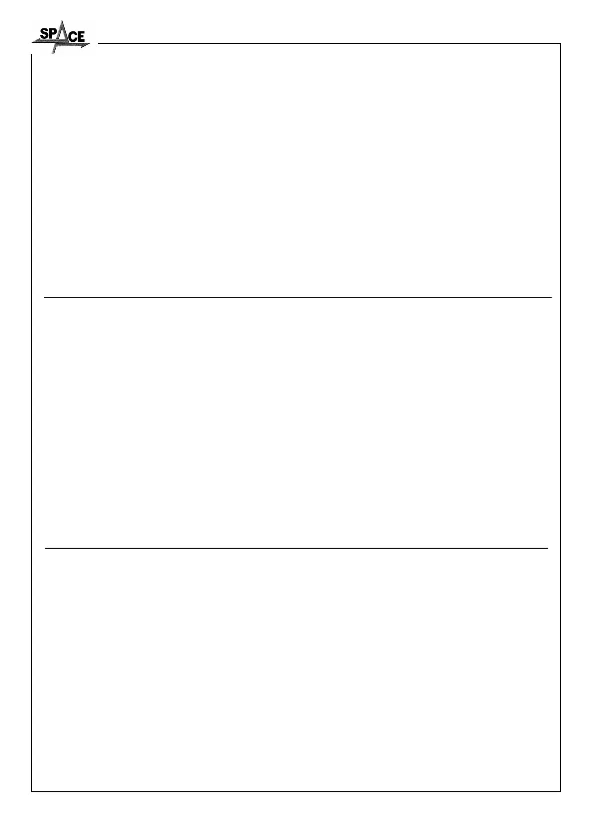
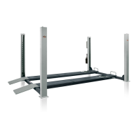
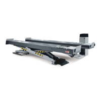
SQ 300 - SQ 350 - SQ 351
SQ 355 - SQ 400 - SQ 401 - SQ 405
SQ 501 - SQ 650 - SQ 800
VERIFICHE DI PRIMA INSTALLAZIONE - SOLLEVATORE TIPO SPACE ...
N° MATRICOLA ...
S Verifica distanza delle pedane dai muri dove è installato (non inferiore a 1500 mm)
S Verifica tensione funi
S Verifica altezza di sollevamento dal piano pavimento a piano pedane (vedi layout pag.14-15-16-17-18-19-20-21-22-23-24)
S Livellamento basi mettendo eventualmente spessori sotto le colonne
S Serraggio tasselli fissaggio colonne
S Serraggio tubi idraulici da centralina a utilizzi
S Controllo livello olio centralina
S Controllo allacciamento rete e collegamento cavi
S Attivazione sicurezze
S Spurgo aria impianto idraulico
S Verifica comandi elettrici (l'interruttore generale, pulsante salita, pulsante discesa)
S Controllo funzionamento cicalino
S Controllo tempi di salita e discesa a pieno carico
DATA
FIRMA INSTALLATORE FIRMA UTILIZZATORE
INITIAL INSTALLATION INSPECTIONS - LIFT TYPE SPACE ...
SERIAL NUMBER...
S Check distance of platforms from any walls (not less than 1500 mm)
S Check cable tension
S Check elevation height from floor to platform surface (see layout pages 14-15-16-17-18-19-20-21-22-23-24)
S Level base, place shims under post feet if needed
S Check that post anchoring bolts are well tightened
S Check that hydraulic lines across hydraulic unit and items are well tightened
S Check oil level in hydraulic unit
S Check mains and cable connections
S Operate safety devices
S Bleed air for hydraulic system
S Check power controls (main switch, rise button, descent button)
S Check buzzer operation
S Check up/down times with full load
DATE
INSTALLER SIGNATURE USER SIGNATURE
KONTROLLEN WÄHREND DER ERSTINSTALLATION - HEBEBÜHNE TYP SPACE ...
SERIENNUMMER ...
S Kontrolle der Distanz der Fahrschienen von Wänden des Einbauorts (nicht unter 1500 mm)
S Seilspannung prüfen.
S Kontrolle der Hebehöhe gemessen vom Boden zur Fahrschienenfläche (siehe Layout Seiten 14-15-16-17-18-19-20-21-
22-23-24).
S Nivellierung der Säulen durch eventuelles Einfügen von Ausgleichsscheiben.
S Anzug der Befestigungsdübel für die Säulen am Boden.
S Anzug der Hydraulikleitungen von der Zentrale zu den Verbrauchern.
S Ölpegelkontrolle in der Zentrale.
S Kontrolle des Netzanschlusses und der Kabelanschlüsse.
S Aktivierung der Sicherheitsvorrichtungen.
S Entlüftung der Hydraulikanlage.
S Kontrolle der elektrischen Steuerungen (Hauptschalter, Hebesteuertaste, Senksteuertaste).
S Kontrolle der Summerfunktion.
S Kontrolle der Anstiegs- und Senkzeiten bei voller Belastung.
DATUM
UNTERSCHRIFT DES INSTALLATEURS UNTERSCHRIFT DES ANWENDERS