21
34
39
28
$#$)$+''# #!
.$#)"#*)*'
)#)$''#$
)"".
*()$)(',
P(#)'#!
*()"#)"#("
*()$+'$'*#'
)
)#"$+#!!
"*()#$)$()'*)
)$'.)),'##
!!
Check system for stability.
B
A
-:081/-:.1
>19;B10-:0?@;>10
.E>19;B5:3<5:
#$)
;B1><8-@1C58825@
"& .-/7.>-/71@
#$)
22
21
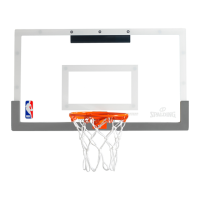
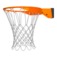
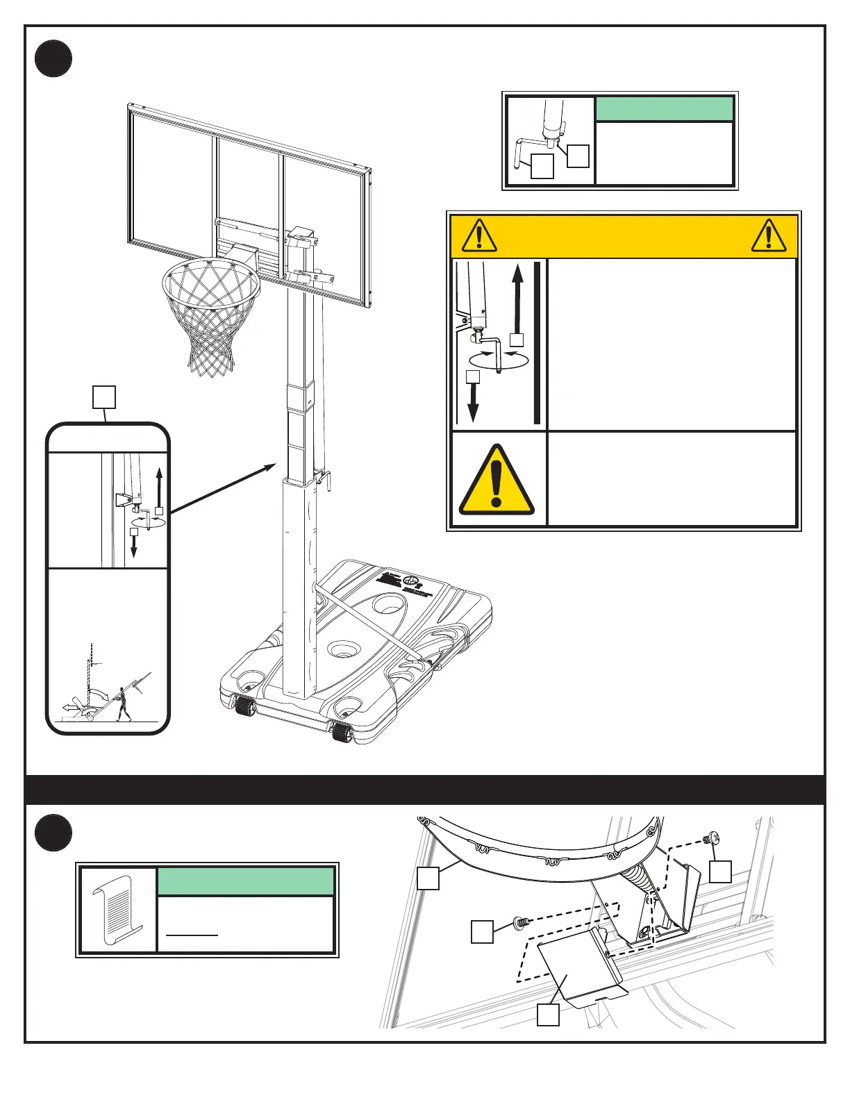
RIM COVER ATTACHMENT
39
*)$#
<<8E1534@06A?@91:@-:0!;B5:3 -.18@;2>;:@;2<;81C41>15@5?/81->8EB5?5.81
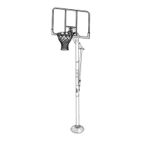
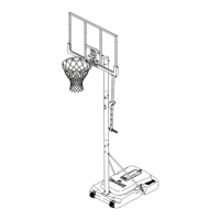
MOVING SYSTEM
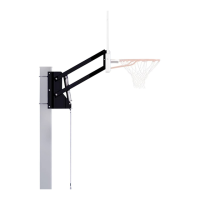
HEIGHT
ADJUSTMENT
1. While holding pole, rotate basketball sytem
f
orward until wheels engage with ground.
2. Move basketball system to desired location.
3. Carefully rotate basketball system upright.
4. Check system for stability.
B
A
Rotate crank
handle to raise
and lower
backboard.
D
o not over crank
h
andle beyond the
m
anufactured height
indicator range of
7-1/2 - 10 feet.
Damage may be
caused to the screw
jack’s internal
adjustment
mechanism if
adjusted over 10 or
under 7-1/2 feet.
33