Do you have a question about the SPALDING Arena Slam Rim and is the answer not in the manual?
| Material | Steel |
|---|---|
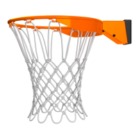
| Rim Diameter | 18 inches |
| Net | Included |
| Size | Official Size |
| Features | Heavy-duty construction |
Critical warnings for safe product operation, emphasizing potential injuries and property damage.
Key safety guidelines for system operation, including ladder use, adult supervision, and height requirements.
Instructions for adult assembly, packaging disposal, and unit filling requirements.
List of all components with quantity, part number, and description for assembly reference.
Visual guide to identify and match hardware components for correct assembly.
Attach the Goal Mount bracket (2) onto the rim bracket.
Insert tee-bolt (3) into goal mount bracket (2) and secure with reinforcement bracket (4).
Attach special nut (7), washer (6), and spring (5) to tee-bolt (3).
Connect rim to board using bolts (8), washers (10), and nuts (11).
Install the net (9) by attaching it to the rim.
Attach spring cover (13) to rim (12) using self-tapping screws (14).
Note on regulation rim height of 10 feet (3.05M).