14 15
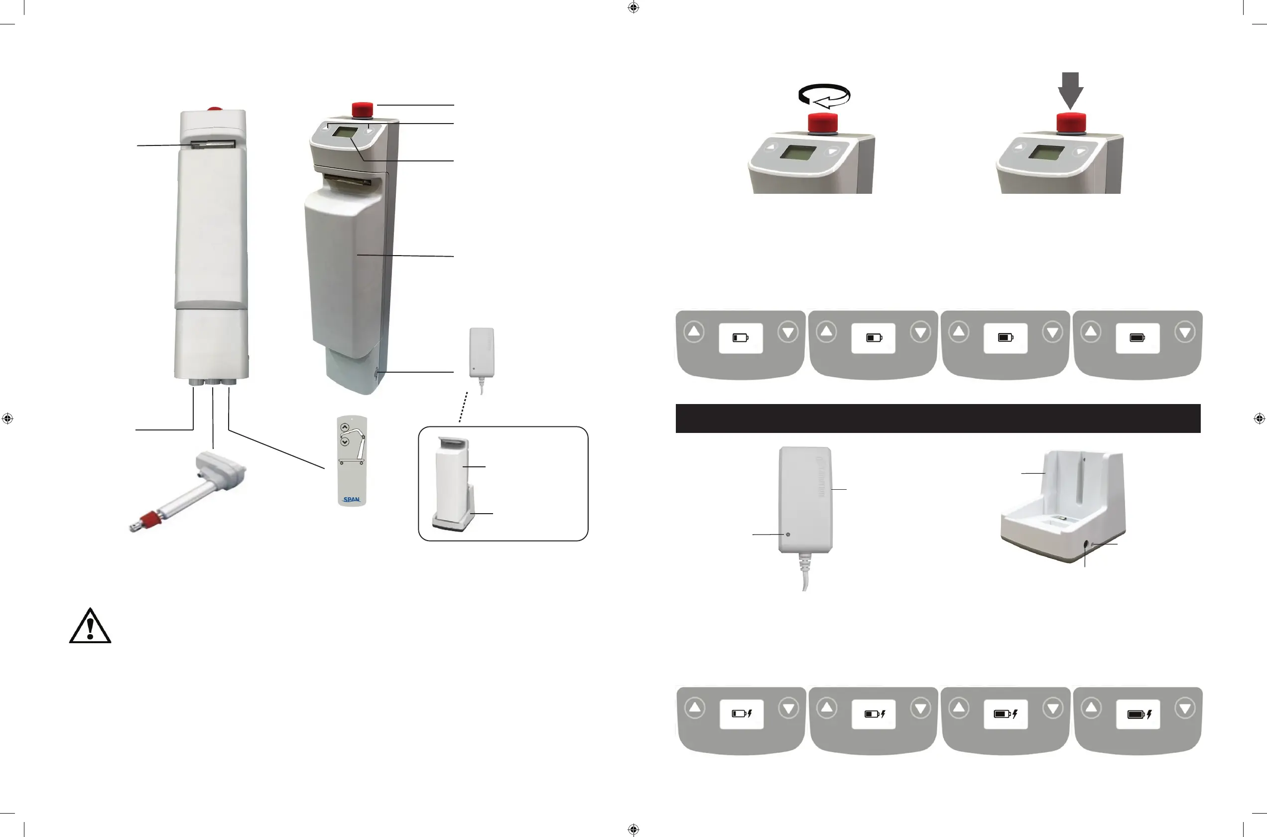
Power Control Unit Overview
1. Connect Actuator as shown above.
2. Connect Hand Control as shown above.
Actuator
Battery Pack
Release Handle
Emergency Stop Button
Up / Down Button
LCD Display Panel
Battery Pack
(P11618)
Charger
DC In
Not Used
Hand Control
Charging Cradle
(Optional)
Additional Battery Pack
(Optional)
(P11619)
WARNING!
• Contains a long charger cord that may cause strangulation if
used improperly
• Keep long charger cord out of walkway where it poses a
tripping hazard
• Have the charger port on the controller facing away from the
wall for easy disconnection
DC Charger
(included)
(P11619)
LED Indicator
* Amber = charging
* Green = charging completed
Charger Plug-in
LED Indicator
* Green = power connected
* Blank = power disconnected
Charging Cradle
(Optional)
(P11617)
LCD Display Panel Signs - Charging
During charging, the LCD Display Panel will show one of the four signs below.
• The DC Charger must be connected.
• The emergency stop button must be released.
• The battery will not be charged if the emergency button is pressed in.
LCD Display Panel Signs
When the emergency stop button is released, the LCD Display Panel will show one of the four
signs below.
• The sign will display for 5 seconds.
• Then the lift will go into standby mode and the sign disappears.
• The lift is ready for use.
Charging: DC Charger or Charging Cradle
Release Pressed in
Actuator
Battery Pack
Release Handle
Emergency Stop Button
Up / Down Button
LCD Display Panel
Battery Pack
Charger
DC In
Not Used
Hand Control
Charging Cradle
(Optional)
Additional Battery Pack
(Optional)