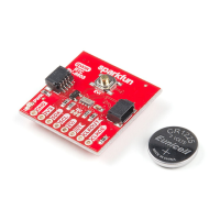
Pin Descriptions
While the Qwiic interface is the easiest and fastest way to start using your RTC, there are several other pins for extra functionality broken out. You will
need to either solder to these pins to make use of them or you can create a temporary connection using something like these IC Hooks. The table below
outlines all of the pins broken out on the RTC and summarizes their functionality.
Pin
Label
Pin
Function
Input/Output Functionality Notes
GND Ground Input 0V/Common Voltage
3.3V Power
Supply
Input Power Supply voltage range is 1.5-3.3V
SDA I C Data
Signal
Bi-directional Bi-directional data line. Voltage should not exceed power supply (e.g. 3.3V).
SCL I C Clock
Signal
Input Master-controlled clock signal. Voltage should not exceed power supply (e.g. 3.3V).
EVI Event
Input
Input/Output External event interrupt pin with Time Stamp Function. Active LOW by default. Tied to the button labeled EVI
for easy use.
2
2
 Loading...