INT Interrupt
Output
Output Open-drain, active LOW. Used to output Alarm, Periodic Countdown Timer, Periodic Time Update and
External Event Interrupt signals. Pulled to 3.3V with 100k resistor.
CLKOUT Clock
Output
Output Programmable square wave output for peripheral devices. Available frequencies are 32.768 kHz (default),
1024 Hz or 1Hz. Set on power-up and controlled by the state of CLKOE pin. When disabled, pin is high
impedance.
CLKOE Clock
Output
Enable
Input Enables and disables the CLKOUT pin. If HIGH, CLKOUT is enabled and is in output mode. If LOW,
CLKOUT is disabled. Pin is pulled to GND by default with a 100k resistor.
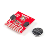
The EVI pin is broken out but also connected to the button highlighted to easily trigger interrupt events like time stamps.
Jumpers
There are two jumpers on the SparkFun Real Time Clock Module - RV-8803 (Qwiic) labeled "I C" and "LED". The I C jumper is closed by default and can
be opened by severing the trace between the three pads to disconnect the two 4.7k Ohm resistors from the SDA and SCL lines. Open this jumper for if
you have many I C devices on the same bus or to reduce current draw for low-power projects. The LED jumper is closed by default and enables the on
board power LED. To open it, simply sever the trace in between the two jumper pads to disconnect the power LED (particularly useful for low-power
applications). Note: The power LED is tied to the 3.3V input and is not powered by the backup battery.
2 2
2
 Loading...