Page 4 MainLine
TM
3.0
Installation
cont'd.
3.2 Mounting Tubes & Saddles
Meterheads can be mounted into a round process line using 1)
a Sparling Model MT1 In-Line Flow Tube or 2) a Sparling Model
MS1 Welding Saddle.
3.2.1 Meterhead with MT1 In-Line Flow Tube (2" - 36")
a. Be sure to read Section 3.1 Site Selection Criteria
prior to installing your meter.
b. Install the meter tube in the line just as though it were
a short length of pipe.
c. The propeller must face the on-coming flow. Arrows
on the meter tube and cover plate will point in the
direction of the flow.
3.2.2 Meterhead with MS1 Welding Saddle (6" - 72")
a. For welding 6"-14" saddles to steel or wrought-iron
pipe, place the saddle on the pipe and scribe a
line INSIDE the saddle.
b. Cut or burn a full opening in the pipe so there will be
no projections of the pipe beyond the straight inside
edge of the saddle. Smooth the pipe around the
opening to make a good surface for the saddle.
c. Cast steel saddles (sizes 6" - 14") should be tacked
first, then welded in place, taking care not to over-
heat any part of the saddle.
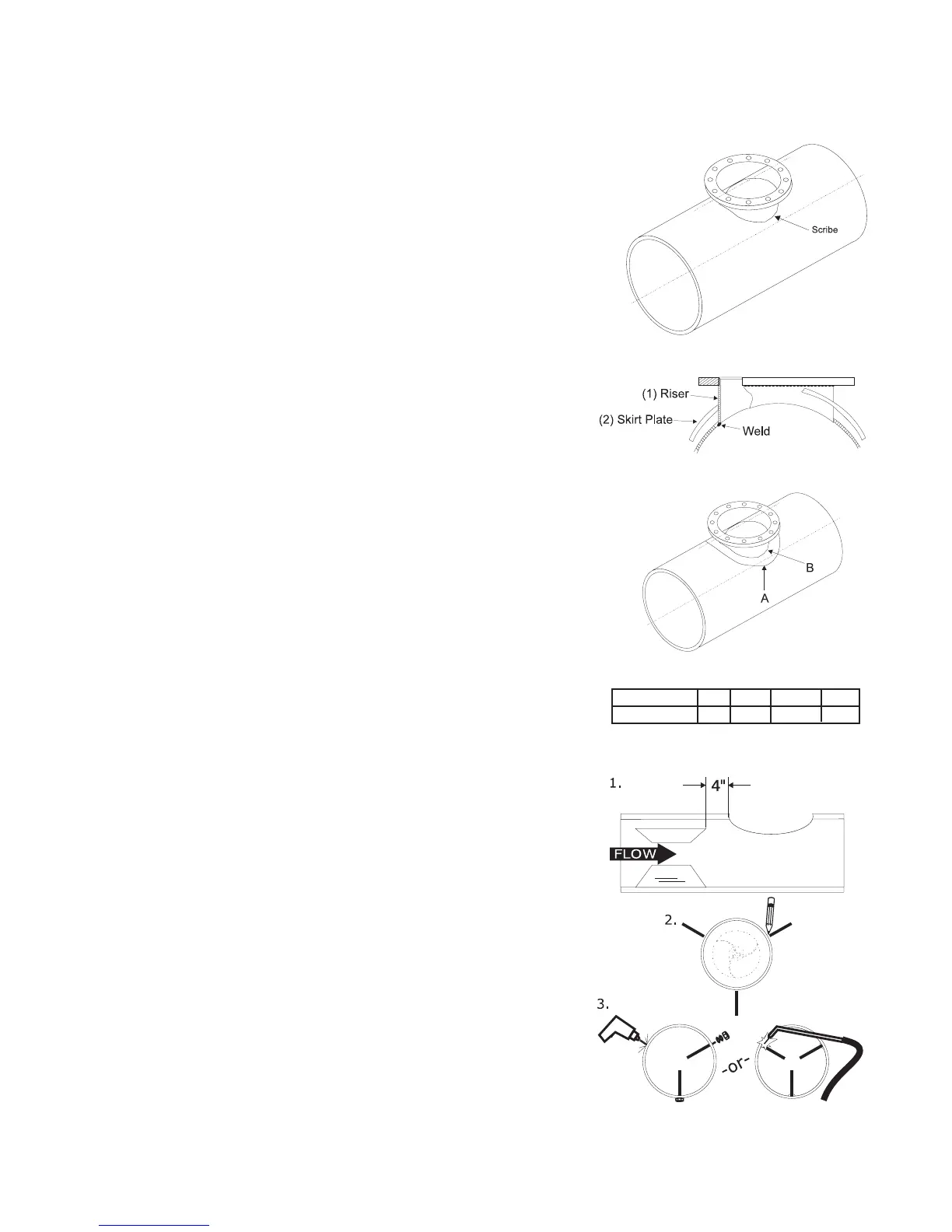
d. Fabricated steel saddles (sizes 16" - 72"):
(i) Place riser on pipe (Fig. 3.2). Scribe around
outside of riser as shown. Cut hole.
(ii) Insert riser into the hole in skirt plate (Fig. 3.3), do
not weld at this point. Pull skirt plate up against
the flange of riser.
(iii)Insert riser into cut-out in pipe. Make sure
bottom edge of riser is flush with I.D. of the
pipe and holes in the flange are straddling the
center line of pipe. Weld riser to inside pipe as
shown.
(iv)Lower skirt plate down onto pipe. Position to
achieve conformity with O.D. of pipe. Weld in a
continuous bead at point "A" and "B".
e. If straightening vanes are required, go
to section 3.2.3. If not, skip to section 3.3
3.2.3 Install straightening vanes (if required)
as shown on Figure 3.5.
Three straightening vanes are required.
Vanes should be equally spaced radially and
parallel with the longitudinal axis of the pipe (1)
Figure 3.4
Figure 3.5
Install Straightening Vanes
Figure 3.2
a. b.
Figure 3.3
Size Meter 6-14 16-30 36 & 42 48-72
Dimension "A" 4 8 12 15
 Loading...