MANIFOLD OPERATION
Each of the 48 holes in the Processor manifold are restricted in order to maintain
the manifold pressure even if all of the positions are not filled by columns. In
addition there are valves located on top of the manifold that shut off individual
rows of 12. With no column in place, there is approximately 0.75 +/- .05 scfh of
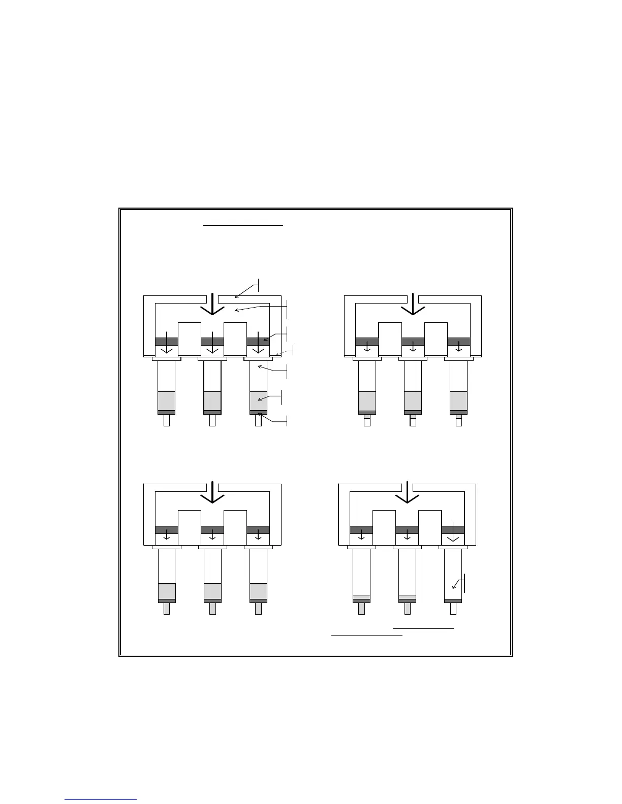
flow through a hole at 25 psig. The principle of the restrictor manifold design is
discussed in the following diagrams.
Input Pressure
P = 30psi
0
psi
0
psi
0
psi
30
psi
30
si
30
psi
Input Pressure
P = 30psi
24
psi
24
psi
24
psi
30
psi
30
psi
30
psi
Input Pressure
P = 30psi
18
psi
18
psi
10
psi
26
psi
26
psi
26
psi
Fig A.
Initial state. M anifold pressure builds to
controller set pressure. The effect of the restrictors is
m inim al in limiting flow from m anifold to colum n
reservoir. Reservoirs start at atmospheric pressure.
Fig B.
Shortly after the initial state, the pressure builds in the
column reservoir due to the fluid being held up by the flow
characteristics of the colum n sorbent bed. Restriction still has
minimal effect. Eventually the pressure builds enough to
overcome the fluid flow resistance and the fluid begins to
pass through the sorbent bed.
Input Pressure
P = 30psi
24
psi
24
psi
24
psi
30
psi
30
psi
30
psi
Fig. C.
Depending on flow characteristics of column
sorbent bed, pressure in column reservoir stabilizes.
Inhibiting the flow with the constrictors at this time is helpful in two ways
: (1) the amount of gas
used is
minimized as compared to a system with no inhibitors. (2) the pressure rem ains high
in the columns containing
liquid as compared to the empty or dry columns.
Fig. D.
When fluid passes through (one or more columns)
com pletely, and there is m inimal pressure drop across the
column bed, the effect of the restrictor is maximized. The
restrictor becomes the primary flow inhibitor of the gas as it
passes through the column to the atmosphere.
manifold
block
manifold
pressure
chamber
gas flow
“restrictor”
SPE column
reservoir
solvent or
sample fluid
sorbent bed
empty
or dry
column
Positive Pressure Control “with flow restrictors”
column seal
The manifold is segmented into 4 rows. Using the 4 toggle switches on the
manifold individual rows of 12 can be turned on or off to save nitrogen. The
adjustable flow reading on the rotometer equates to the total flow to the turned
on rows.
 Loading...