Speck Pumpen Vakuumtechnik GmbH
zertifiziert: DIN EN ISO 9001
Supplementary Operating Instructions for Explosion Protection
8
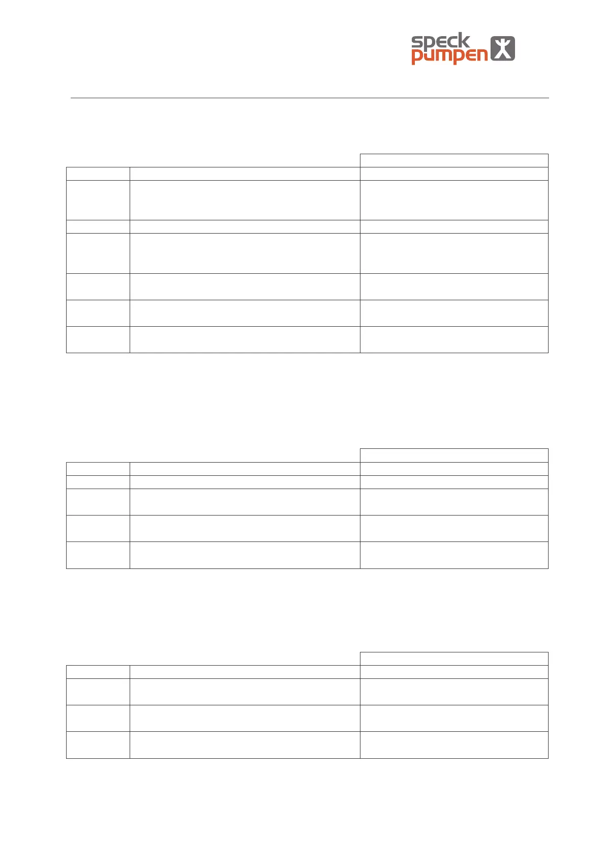
7.1.1 MCR-equipment for compressors of the equipment category 1G (inside) / 2G/D (outside)
comp. Fig. 7.1 When to install:
Motor protection switch (comp. 2) Always
LS- 01 Liquid level switch for clearance to start in the
compressor
If suction- and pressure-casing do not
ever have an appropriate piping to the
separator tank
LS- 02 upper liquid level switch in the separator tank Always
LS- 03 lower liquid level switch in the separator tank If LS- 01 is not installed or the liquid
level in the separator tank fluctuates
significantly.
FS- 04 Flow rate switch in the operating liquid supply of
the compressor
Always
TS+ 05 Temperature switch on the pressure side of the
compressor
Always
PS+ 06 Pressure switch on the pressure side of the
compressor
If the compression via ambient
pressure is not excluded due to use
• For compressors with double-action slide ring gasket, section 7.1.3 is also to be taken into
consideration
• For compressors with magnet coupling, section 7.1.4 is also to be taken into consideration
• With the conveying of gas-vapour mixtures, which contain hydrogen, an inertisation according to
section 7.2.2 is to be taken into consideration
7.1.2 MCR-equipment for compressors of equipment category 2G/D (inside) / 2G/D (outside)
comp. Fig. 7.1 When to install:
Motor protection switch (comp. 2) Always
LS- 02 upper liquid level switch in the separator tank Always
LS- 03 lower liquid level switch in the separator tank If the liquid level in the separator tank
fluctuates significantly.
TS+ 05 Temperature switch on the pressure side of the
compressor
Always
PS+ 06 Pressure switch on the pressure side of the
compressor
If the compression via ambient
pressure is not excluded due to use
• For compressors with double-action slide ring gasket, section 7.1.3 is also to be taken into
consideration
• For compressors with magnet coupling, section 7.1.4 is also to be taken into consideration
7.1.3 MCR-equipment for compressors of equipment category 2G/D (outside)
comp. Fig. 7.1 When to install:
Motor protection switch (comp. 2) Always
FS- 04 Flow rate switch in the operating liquid supply of
the compressor
Always
TS+ 05 Temperature switch on the pressure side of the
compressor
Always
PS+ 06 Pressure switch on the pressure side of the
compressor
If the compression via ambient
pressure is not excluded due to use
• For compressors with double-action slide ring gasket, section 7.1.3 is also to be taken into
consideration
• For compressors with magnet coupling, section 7.1.4 is also to be taken into consideration