Do you have a question about the Speedaire 1WD36 and is the answer not in the manual?
Details the meaning of DANGER, WARNING, and CAUTION symbols for hazard identification.
Highlights critical warnings against using the compressor for breathing air or for non-approved purposes.
Guidelines for compressor location, mounting on level ground, and avoiding obstructions.
Details on power supply, wiring, grounding, and magnetic starter for safe electrical connection.
Highlights vital warnings regarding unit damage, isolating valves, pressure regulators, and environmental conditions.
Details the wiring diagram and emphasizes correct motor rotation for safe operation.
Provides recommendations for air line sizing, connections, and warnings about material selection.
Step-by-step guide for initial startup, including power connection and oil level check.
Warning that the unit can start automatically without prior notice.
Daily checks include oil level, draining tank moisture, and powering off the unit.
Weekly tasks involve cleaning components, cleaning air filters, and checking V-belt tension.
Periodic maintenance includes changing oil, checking for air leaks, tightening fasteners, and cleaning valves.
Maintenance for pressure relief valve, automatic tank drain, pressure switch, and belts.
Focuses on maintenance of compressor valves, centrifugal unloader, and check valve.
Warning regarding safe removal and servicing of the check valve.
Details on Speedaire's recommended 30-weight, non-detergent industrial oil and synthetic lubricant.
Step-by-step guide for transitioning from mineral oil to synthetic lubricant.
Warning about oil emulsification indicating potential moisture issues or an oversized compressor.
Outlines the one-year warranty for the pump and receiver, and three-year for the pump.
Covers limitations of liability, warranty disclaimers, and advice on product suitability.
Explains the procedure for prompt disposition and filing warranty claims.
Troubleshooting steps for motor not starting or starter tripping repeatedly.
Diagnoses slow or fast pressure build-up, and relief valve popping.
Addresses air leaks from the unloader and check valve issues.
Troubleshooting for unloader leaks, belt wear, and compressor overheating.
Diagnoses problems like excessive oil consumption, automatic drain failure, and timer screw leaks.
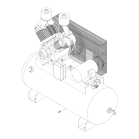
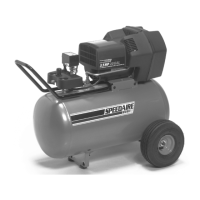
Illustration of the main compressor unit, including pump, motor, and tank.
List of parts for the compressor pump, motor, pulleys, and belts.
Parts list for air receiver, piping, valves, fittings, and electrical components.
Illustrations showing the compressor pump and its immediate connections.
Parts list for aftercooler, discharge tubes, and fittings for specific models.
Parts list for automatic tank drain, drain valves, and various pipe fittings.
Illustration of the 1WD30 compressor pump and its many detailed parts with reference numbers.
List of parts for the crankcase, bearings, governor, and connecting rod assemblies.
Parts list for the centrifugal unloader, muffler, flywheel, and related fasteners.
List of parts for pistons, piston rings, cylinders, intake/discharge valves, and manifolds.
Parts list for gasket sets, filter elements, and complete pump kits.
Parts list for breather tubes, intercooler components, and associated fittings.
List of parts for discharge tubes, relief valves, and compression fittings.
| Model | 1WD36 |
|---|---|
| Max. Pressure | 125 PSI |
| Horsepower | 1.5 HP |
| Pump Type | Oil Lubricated |
| Noise Level | 78 dB |