EasyManua.ls Logo

Speedaire 1WD37 User Manual

Default Icon
72 pages
To Next Page IconTo Next Page
Page #1 background imageLoading...
Page #1 background image
Form 5S5938 Printed in U.S.A. Ver. 04 03/11/2011
02571
0410/034/VCPVP
Operating Instructions & Parts Manual 1WD36, 1WD37, 1WD38, 1WD40, 1WD44
Please read and save these instructions. Read carefully before attempting to assemble, install, operate or maintain the product described.
Protect yourself and others by observing all safety information. Failure to comply with instructions could result in personal injury and/or
property damage! Retain instructions for future reference.
Speedaire
®
20, 25 & 30 HP
Two-Stage Air Compressors
Description
Speedaire compressors are two-stage splash lubricated heavy-duty industrial
units designed for 80%/ON 20%/OFF duty cycle. Maximum operating
pressure is 175 PSI. Each model is equipped with ASME air receiver, ASME
pressure relief valve, three phase electric motor and pressure switch for
start/stop control.
Simplex Horizontal
MODEL 1WD36
Specifications
Model HP
Volts,
Phase
Amp
Draw
Free Air
CFM @
175 psi
Oil
Cap.
(Qts.)
Tank
Cap.
(Gal.)
Tank
Style *
Tank
Outlet
Maint.
Kit
Pump
1WD36 20 230/460, 3 48/24 76.7 7 120 H 1 ¼
FNPT 1WF48 1WD30
1WD37
25
200/208
,
3
74/73
90.1
7
120
H
1
¼
FNPT
1WF48
1WD30
1WD38 25 230/460, 3 62/31 90.1 7 120 H 1 ¼ FNPT 1WF48 1WD30
1WD40 25 230/460, 3 62/31 90.1 7 120 H 1 ¼
FNPT 1WF48 1WD30
1WD44 30 230/460, 3 72/36 101.0 7 120 H 1 ¼ FNPT 1WF48 1WD30
(*) H = Horizontal
C289-C
(Ref. Drawing)
E
N
G
L
I
S
H
E
S
P
A
Ň
O
L
F
R
A
N
Ç
A
I
S
Question and Answer IconNeed help?

Do you have a question about the Speedaire 1WD37 and is the answer not in the manual?

Speedaire 1WD37 Specifications

General IconGeneral
BrandSpeedaire
Model1WD37
CategoryAir Compressor
LanguageEnglish

Summary

Product Description

Compressor Overview

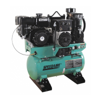
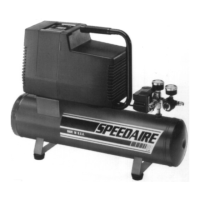
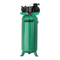
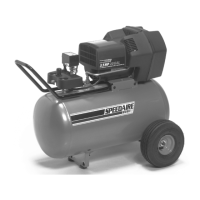
Details on the Speedaire two-stage air compressors and their features.

Safety and Precautions

Safety and Operation Precautions

General safety rules and precautions for operating the air compressor unit.

Safety Symbols and Decals Explained

Explanation of DANGER, WARNING, and CAUTION symbols and decals.

Installation and Setup

General Installation Guidelines

Instructions for unit placement, leveling, and environmental considerations.

Electrical Power Supply Requirements

Details on voltage, wire sizing, and wiring practices for safe power connection.

Air Line Piping Recommendations

Guidance on pipe sizing, connections, and leak prevention for air lines.

Operating the Compressor

Initial Start Up Procedure

Step-by-step guide for the first-time startup and initial operation checks.

Maintenance Schedule and Procedures

Daily Maintenance Tasks

Routine checks and actions to perform each day.

Weekly Maintenance Tasks

Tasks to be completed on a weekly basis for upkeep.

90 Days or 500 Hours Maintenance

Periodic maintenance tasks based on time or usage.

General Maintenance Notes

Important notes on maintaining specific components like motors and valves.

Pressure Relief and Check Valve Maintenance

Specific procedures for maintaining pressure relief and check valves.

Lubrication and Oil Specifications

Lubrication Instructions

Guidance on filling crankcase and recommended lubricant types.

Compressor Oil Specifications

Details on recommended oil type, viscosity, and properties.

Changing To Synthetic Lubricant

Steps for converting from mineral oil to synthetic lubricant.

Limited Warranty Information

Dayton One-Year Limited Warranty

Details of the warranty coverage for the compressor and its parts.

Limitation of Liability

Disclaimers regarding consequential and incidental damages.

Warranty Disclaimer

Information on product accuracy and implied warranties.

Technical Advice and Recommendations Disclaimer

Disclaimer on technical advice provided by the manufacturer.

Product Suitability and Compliance

Information on product compliance with local codes and regulations.

Prompt Disposition for Claims

Procedure for handling warranty claims and product defects.

Troubleshooting Guide

Repair Parts Information

General Parts Illustration

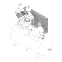
Diagram showing general assembly of compressor models.

General Parts List

List of part numbers and quantities for general models.

Model 1WD30 Parts Illustration

Diagram showing assembly specific to Model 1WD30.

Model 1WD30 Parts List

List of part numbers for Model 1WD30 compressor pump.

Related product manuals