Do you have a question about the Speedaire 1WD40 and is the answer not in the manual?
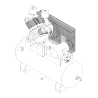
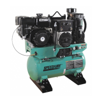
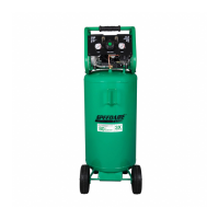
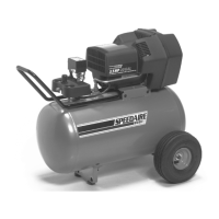
Overview of Speedaire two-stage air compressors, their design, and key features like operating pressure.
Table detailing technical specifications for different models, including HP, voltage, CFM, and tank size.
Essential safety precautions for operating and maintaining the air compressor to prevent injury or damage.
Detailed warnings regarding electrical grounding, cable handling, pressure limits, and tool usage.
Explanation of DANGER, WARNING, and CAUTION symbols indicating different levels of risk.
Advisories on compressor usage for breathing air, as a booster pump, or with special options.
Proper placement, leveling, and securing of stationary compressors for optimal performance and safety.
Guidance on selecting appropriate wiring, voltage, and branch circuit protection for the compressor.
Diagram illustrating the wiring connections for the magnetic starter and motor.
Guidelines for connecting air lines, including union connections, water drop legs, and recommended pipe sizes.
Explanation of the compressor's duty cycle and automatic pressure switch operation.
Step-by-step guide for the first-time startup, including checks, connections, and initial run.
Routine checks including oil level, tank drain, and shutting down the unit.
Cleaning components, checking intake filters, and adjusting V-belts for optimal performance.
Tasks like oil changes, checking for air leaks, tightening fasteners, and servicing valves.
Notes on electric motor service, pressure relief valve, automatic tank drain, and pressure switch.
Instructions for maintaining belts, compressor valves, unloaders, check valves, and interstage relief valves.
Guidelines for filling crankcase, recommended lubricants, and oil specifications for various temperatures.
Step-by-step procedure for changing from mineral oil to synthetic lubricant for the compressor.
Details of the warranty coverage for the compressor pump, air receiver tank, and parts.
Information on liability limitations, disclaimers, technical advice, and product suitability.
Symptoms, possible causes, and corrective actions for motor not starting or starter tripping repeatedly.
Troubleshooting steps for slow pressure build-up, pressure relief valve popping, and air leaks from the unloader.
Diagnosing and fixing air leaks from the unloader and excessive belt wear.
Addressing compressor overheating, excessive oil consumption, and automatic tank drain failures.
Illustrated view of the compressor unit with numbered parts for identification.
Detailed list of parts for the compressor, including part numbers and quantities for various models.
Illustrated view of the compressor pump with numbered parts for reference.
Detailed list of parts for the compressor pump and aftercooler, with part numbers and quantities.
Illustrated view of compressor pump components with numbered parts for identification.
Detailed list of internal pump components, including bearings, rods, pistons, and seals with part numbers.
Detailed list of parts for pump pistons, cylinders, valves, and manifolds with part numbers.
Illustrated view of pump discharge tubes, intake, and fittings with numbered parts.
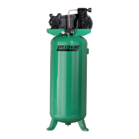
| Model | 1WD40 |
|---|---|
| Voltage | 120V |
| Amperage | 15A |
| Max. Pressure | 135 PSI |
| Pump Type | Oil-Free |
| Tank Capacity | 20 Gallons |