Do you have a question about the Speedaire 1WD44 and is the answer not in the manual?
Comprehensive safety guidelines for operating and maintaining the air compressor unit.
Indicates immediate hazards resulting in severe injury or death.
Indicates hazards or unsafe practices resulting in severe injury or death.
Indicates hazards or unsafe practices resulting in compressor damage or minor injury.
Guidelines for proper placement, ventilation, and environmental conditions for the unit.
Requirements for power supply, wiring, and electrical connections.
Step-by-step instructions for the first-time startup and initial operation.
Routine checks and tasks to be performed daily for optimal performance.
Tasks and inspections to be carried out weekly for continued operation.
Periodic maintenance tasks to be performed every 90 days or 500 hours of use.
Information and precautions regarding the automatic pressure relief valve.
Troubleshooting and maintenance for compressor valves.
Explanation of the centrifugal unloader and its pressure release valve.
Guidance on the function and maintenance of the check valve.
Procedure for converting from mineral oil to synthetic lubricant.
| Brand | Speedaire |
|---|---|
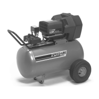
| Model | 1WD44 |
| Category | Air Compressor |
| Language | English |