4 SpeedTech Lights, Inc © 2023
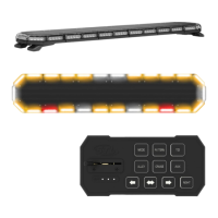
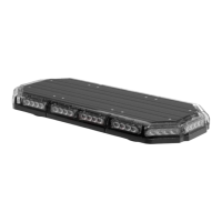
K-FORCE
®
TOW 55
FULL LIGHT BAR
Stop / Tail / Turn Wiring Diagram
Wire Color Function
Red
Stop / Turn Driver Side
Black
Stop / Turn Passenger Side
Yellow
Tail
Specications
Voltage
12 VDC
Amps < 18.2
Optic TIR
LED Count 104
Cable Length 12’ Light Bar Cable, 12.5’ Cig Plug Cable, 12.5’ AUX Cable
Tow Cable Length 8’ Tow Cable
Flash Patterns 30
AUX Wiring Diagram
Wire Color Function
Red
AUX Positive
Blue
AUX Negative
White
Control box back light *
* Only functional when using in conjunction with STL Supreme Control Box (Sold separately)
Wiring Diagram
Wire Color Function
Red (Thick)*
Positive
Black (Thick)*
Negative
Brown
Forward Facing Lights
Light Blue
Rear Facing Lights
Purple
Full 360° Warning Lights Mode 1
Yellow
Flash Pattern
Light Green
Take Down
Green
Alley
* Indicates a main power cable.
Wire Color Function
Blue
Left Arrow
White
Center Out Arrow
Orange
Right Arrow
Grey
Cruise Lights (4 Corners)
Red (Thin)*
Control Box In Positive
Black (Thin)*
Control Box In Negative
Peach
No function
Yellow/Green
Full 360° Warning Lights Mode 2
NOTE: All cables except Negative contact +12 VDC.
NOTE: Flash Mode 2 function can only be activated while Flash Mode 1
cable is receivng +12VDC too.