5 SpeedTech Lights, Inc © 2023
K-FORCE
®
TOW 55
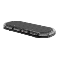
FULL LIGHT BAR
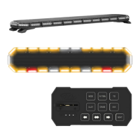
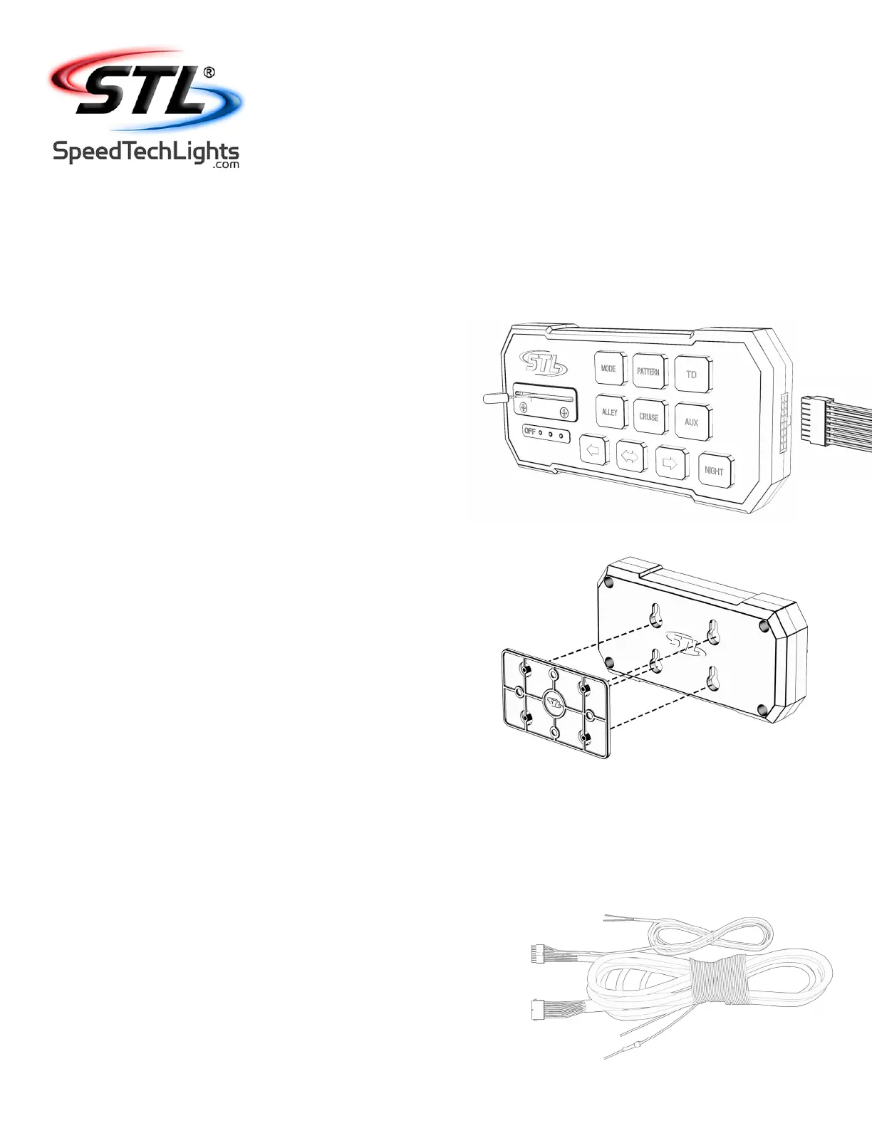
Supreme Control Switch Box Operation (Sold Separately)
Slide Switch:
• O position: Turns o warning functions of the Light Bar.
• 1st position: Powers only the back of the Bar and rear facing 45° warning modules.
• 2nd position: Powers only the front of the Bar and forward facing 45° warning modules.
• 3rd position: Powers all warning functions of the Light Bar.
Mode Button:
• Activates warning in memory mode 2.
Take Down Button*:
• 1st press: TD Steady Burn On.
• 2nd press: TD O.
Alley Button*:
• 1st press: Alley Steady Burn On.
• 2nd press: Alley O.
Trac Advisor Buttons*:
• Trac Advisor LEDs will ash in sequence with warning mode when not activated.
• Left Arrow: Right to Left Trac Sweep.
• Center Out Arrow: Center Out Trac Sweep.
• Right Arrow: Left to Right Trac Sweep.
Flash Pattern Button:
• Cycles to the next ash pattern with each press.
• Non-Volatile memory recalls the last ash pattern selected in each Mode.
• Hold for 2 seconds to toggle Steady Burn mode.
• Hold for 3 seconds to toggle Random pattern mode.
Cruise Button (45° (Four Corner) Modules)*:
• 1st press: Cruise Steady Burn On.
• 2nd press: Cruise O.
AUX Button*:
• Toggle power to AUX cables On and O.
Night Button**:
• Activate back light LEDs in control box.
* Warning lights do not need to be activated for these Buttons to function.
* * Hardwire the free standing cable to your headlight +12VDC line to automate
this feature. NOTE: Once hardwired, this button ceases to function. Make sure the Night button is NOT toggled
before doing this step otherwise the button will constantly remain activated.
Back Plate Mount:
• Included with Supreme Control Switch Box purchase.
Extension Cable (Sold Separately)
• If you have an extension cable with connectors, connect the corresponding ends to
one another. Use the connector at the end of the cable to plug into the control box.
• If you have an extension cable with one connector, you will need to cut the connector
o of the main cable harness coming out of the Light Bar. Save it as a spare part.
You will solder and heat shrink each wire within the cable harness to each wire in the
extension cable harness. DO NOT cross connect wires. Use the connector at the end
of the extension cable to plug into the control box.
• If you have an extension cable with no connectors, you will need to cut in the middle
of the main cable harness coming out of the Light Bar. You will solder and heat shrink
each wire within the cable harness to each wire in the extension cable harness. DO
NOT cross connect wires. Use the reattached connector from the end of the main
cable harness to plug into the control box.
• NOTE: DO NOT leave connectors, cables, solder points exposed to heat, moisture, or
debris.
 Loading...