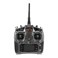
BATTERY LED MONITOR
AgreenLEDbatterymonitorislocatedonthefrontleft
of the transmitter next to the on/off switch. When the
batteryvoltageisabove5voltstheLEDwillbesolid
green indicating that the battery has sufficient operational
voltage.Below5voltsthegreenLEDwillbegintodim,
indicating the battery is low. When the voltage drops
below4volts,thegreenLEDwillturnoffandonlythe
redLEDwillbelit,indicatingthebatteriesshouldbe
replaced immediately.
SolidGreen-Batteryisgood
DimGreen-Batteryvoltageislow
NoGreen,onlySolidRed-Batteryvoltageiscritically
low.Replacebatteries
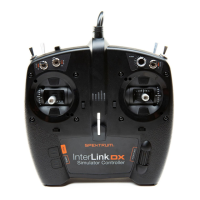
OPTIONAL RUBBER GRIPS
The DX3E is supplied with a medium-size grip installed
on the transmitter. Optional small and large grips are
available(SPM9006)tofitpreferencesandhandsizes.
Each grip’s size is identified with an “S” (small), “M”
(medium),or“L”(large)ontheinsideofthegripfor
easy identification. To remove, simply lift the edge of the
grip and continue around the grip until it is completely
removed. To replace, align the tabs of the grip to the slots
in the handle and press the grip in place.
RECEIVER COMPATIBILITY
The DX3E features DSM technology and is compatible
with Spektrum DSM and DSM2 surface receivers and the
marine receiver.
COMPATIBLE SPEKTRUM RECEIVERS
The DX3E is compatible with the following receivers.
Note: TheDX3Eoperatesin16.5msframerate.
DSM
SR300-3-channelSport-SPMSR300
SR3001-3-channelPro-SPM1205
SR3300T-3-channelwithbuilt-intelemetry- SPMSR3300T
SR3500-3-channelMicroRace-SPM1210
Note:TheSR3000HRS(SPM1202)receiver
is designed to be used with Spektrum’s Futaba
HRScompatiblemodulesystemonlyandis
not compatible with the DX3E.
DSM2
SR3100-3-channelPro-SPMSR3100
SR3520-3-channelMicroPro-SPMSR3520
Marine
MR3000-3-channelMarine-SPMMR3000
PleasenotethatDSM2andmarinecompatible
transmitters can be identified by the following logo
located on the back of the transmitter:
RECEIVER CONNECTION AND
INSTALLATION
Typical Electric Installation
Typical Gas Installation
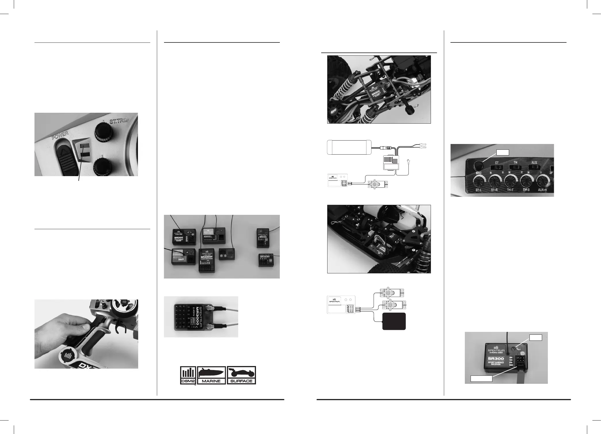
BINDING A RECEIVER
1.WiththereceiveroffinsertthebindplugintotheBND
port on the receiver.
2.Powerthereceiverthroughanyotherport.Theamber
LEDwillflashcontinuously,indicatingthereceiveris
in bind mode.
3.Withthesteeringwheel,throttletriggerandAux
channel (if applicable) in the desired preset failsafe
positions, press and hold the bind button and turn
onthetransmitter.TheredLEDonthefrontof
the transmitter will flash within a couple seconds
indicating the transmitter is in bind mode. Once the
redLEDbeginsflashing,releasethebindbutton.
4.Within15seconds,theLEDonthereceiverwillgo
solid indicating a successful bind has taken place.
5.Removethebindplugandstoreitinaconvenient
place.
Note: You must rebind when:
•Differentfailsafepositionsaredesired,e.g.when
throttle or steering reversing has been changed.
•Changingreceivertypes,e.g.changingfromaDSM
receiver to a DSM2 or Marine receiver.
•Thereceiveristobeboundtoadifferenttransmitter.
Note:SomeSpektrumreceivers,liketheSR3000,usea
bind button rather than a bind plug. The binding process
is the same with this receiver; however, instead of
inserting the plug before powering up the receiver, press
and hold the bind button while powering up the receiver
to enter bind mode.
Bind Plug
LED
Bind

 Loading...