Do you have a question about the Sperre HV2/210 and is the answer not in the manual?
| Brand | Sperre |
|---|---|
| Model | HV2/210 |
| Category | Air Compressor |
| Language | English |
Details required for ordering replacement parts, including type, serial number, part number, and quantity.
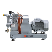
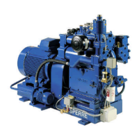
Explains the single-cylinder, 2-stage, water-cooled design and air circulation through the compressor.
Details safety valves, cylinder block cooling jacket safety plate, and pressure switch for oil pressure.
Guidance on compressor placement, ambient temperature, foundation, alignment, and piping to avoid water pockets.
Importance of reliable cooling water supply, circulation checks, and recommended water temperatures.
Step-by-step instructions for initial start-up and after long periods of disuse, including checks and run-in.
Monitoring pressures and temperatures, automatic features, and draining condensate from coolers and traps.
Manual stopping for short periods and long-term shutdown procedures, including preservation.
Diagnosing and resolving issues like low/no pressure, safety valves blowing, and blocked valves.
Addressing overheating, knocking, piston scoring, and excessive lube oil consumption with their causes and solutions.
Details scheduled maintenance routines (A-F) based on operating hours for checks and overhauls.
Procedures for inspecting, cleaning, and overhauling valves, including replacement of worn parts and springs.
Details on replaceable plain bearings (big-end, main, gudgeon pin), their lubrication, and fitting procedures.
Procedures for dismantling and aligning the flexible coupling between the compressor and motor.
Lists recommended mineral and synthetic oils based on manufacturer tests for reliable compressor operation.
Importance of keeping coolers free of deposits, cleaning procedures, and when to replace the entire cooler.
Instructions for cleaning the air filter and recommended replacement interval for the oil filter.
Table T.1 provides coolant flow rates and pressure drop data across the compressor at different speeds and pressures.
Table T.2 lists recommended operating pressures, temperatures for cooling water, and lube oil.
Table T.3 specifies torque values for various components, including thread diameter and key width.
Table T.4 details clearance specifications for valves, piston-cylinder, bearings, and crankshaft play.
Table T.5 provides data on piston ring counts, end clearance, and wear limits for LP and HP stages.
Table T.6 lists general compressor specifications like cylinder/piston diameters, stroke, bearing sizes, and oil capacity.
Detailed list of replacement parts for various valves, including suction, delivery, and associated components.
Diagram showing air flow through the compressor stages, valves, and coolers, labeled A through I.
Illustrates the method for checking radial and parallel misalignment of the compressor and motor coupling.
Diagram showing piston components labeled with numbers 1, 2, 3, 4 for identification.
Diagram illustrating how to measure piston ring end clearance 'S' for wear assessment.
Diagrams for LP suction and delivery valves showing parts for assembly and identification.
Diagrams for HP suction and delivery valves showing parts for assembly and identification.