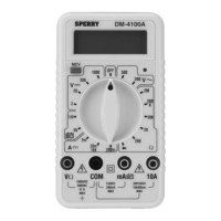
3. Raise the "COM" terminal potential above 500V to ground.
4. Energize the circuit. If the reading is within the next lower range,
switch to that range after completely de-energizing the circuit
under test. Continue changing to lower ranges if the reading is
within the next lowest range to obtain the best accuracy.
5. Completely de-energize the circuit before removing the test
leads.
Sec. 9.3
RESISTANCE MEASUREMENTS
1. Insert the black and red test leads into the respective "COM"
and "V-W" terminals.
2. Place the range selector switch into the W range desired for a
measurement.
CAUTION
All resistance measurements should be taken on de-energized cir-
cuits only. To avoid possible electric shock, instrument damage and/or
equipment damage do not connect the "COM" and "V-Ω" terminals to cir-
cuits having a potential difference exceeding 250VDC/AC. Do not con-
nect the "COM" terminal to potentials exceeding 500V to ground.
3. Completely de-energize the circuit or device, which is to be
measured. Connect the test leads to the device (the red test
lead is positive with respect to the black test lead). A reading of
1 indicates an overrange condition. This will occur with the
test leads open on all resistance ranges. If overrange occurs
when taking a reading, switch to the next highest range.
Sec. 9.4
BATTERY TEST MEASUREMENTS
1. Insert the black and red test leads into the respective "COM"
and "mA" terminals for 1.5Vdc and 9Vdc.
2. Place the range selector switch into the 1.5V or 9V battery test
range. The load current it approximately 200mA at 1.5Vdc and
6mA at 9Vdc.
13

 Loading...