EasyManua.ls Logo

Sperry instruments DM4050 User Manual

Sperry instruments DM4050
5 pages
To Next Page IconTo Next Page
Page #1 background imageLoading...
Page #1 background image
I. DISPLAY FUNCTIONS &
SYMBOLS
Diode Test Battery Test
AC - Alternating Current mA - Millamp
DC - Direct Current A - Amp
Ohm - Resistance OFF Power Off
Rotary Switch
LCD Display
COM Terminal
Backlight
Transistor Connector
Figure 1
Input Terminal
ON / OFF Button
Rotary Switch
OPERATING INSTRUCTIONS
Digital
Multi-Meter
DM4050
Read this owner’s manual thoroughly before use and save.
II. SAFETY WARNINGS
This instruction manual contains warnings and safety rules which must be observed by
the user to ensure safe operation of the instrument and retain it in safe condition.
• Read through and understand the instructions contained in this manual before using the instrument.
• Keep the manual at hand to enable quick reference whenever necessary.
• The instrument is to be used only in its intended applications.
• Understand and follow all the safety instructions contained in the manual.
• It is essential that all safety instructions are adhered to.
• Failure to follow the safety instructions may cause injury, instrument damage
The symbol indicated on the instrument means that the user must refer to the related parts in the
manual for safe operation of the instrument. It is essential to read the instructions wherever the symbol
appears in the manual.
1
Question and Answer IconNeed help?

Do you have a question about the Sperry instruments DM4050 and is the answer not in the manual?

Sperry instruments DM4050 Specifications

General IconGeneral
TypeDigital Multimeter
Resistance MeasurementYes
Capacitance MeasurementYes
Frequency MeasurementYes
Data HoldYes
Auto Power OffYes
DC Voltage Ranges200mV, 2V, 20V, 200V, 600V
AC Voltage Ranges200V, 600V
DC Current Ranges200µA, 2mA, 20mA, 200mA, 10A
Diode TestYes
Continuity TestYes
Overload ProtectionYes
Battery9V
Max Voltage600V
Max Current10A
Resistance Ranges200Ω, 2kΩ, 20kΩ, 200kΩ, 2MΩ
Battery TestYes
Capacitance Range2nF, 20nF, 200nF, 2µF, 20µF
Frequency Range20kHz

Summary

Display Functions and Symbols

Rotary Switch Functions

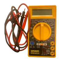
Details symbols and functions for various rotary switch settings like Diode Test, AC/DC voltage, and resistance.

Operating Instructions

DC and AC Voltage Measurement

Guides on connecting leads, setting range, and performing DC and AC voltage measurements.

DC Current Measurement

Instructions for measuring DC current, including lead connection and range selection for different amperage levels.

Resistance Measurement

Steps for measuring resistance, emphasizing circuit power-off and capacitor discharge before testing.

Diode and Transistor Measurements

Procedures for testing diodes by checking forward voltage drop and measuring transistor hFE values.

Back-light Function

Information on how to activate the meter's back-light feature using the LIGHT button.

Battery and Fuse Replacement

Battery and Fuse Maintenance

Guidelines for replacing the battery when indicated and locating the fuse for replacement.

Warranty Information

Limited Lifetime Warranty

Details on the limited lifetime warranty, exclusions, and claim procedures for Sperry Instruments products.

Related product manuals