EasyManua.ls Logo

Sperry instruments DM6800 - User Manual

Sperry instruments DM6800
6 pages
Print Icon
To Next Page IconTo Next Page
Loading...
1
OPERATING INSTRUCTIONS
Thin Autoranging Multimeter
DM6800
Rotary Switch
OFF
Power off Resistance Measurement
AC Voltage Measurement Continuity Measurement
DC Voltage Measurement AC/DC Current Measurement
A
A
400A
400A
A
A
400A
400A
A
A
400A
400A
Read this owners manual thoroughly before use and save.
IMPORTANT: RECEIVING INSTRUCTIONS
Visually inspect all components for shipping damage. If you find damage, notify the carrier at once.
Shipping damage is NOT covered by warranty. The carrier is responsible for all repair or replacement costs resulting from damage in shipment.
1.0 DISPLAY FUNCTIONS & SYMBOLS
1.1 FUNCTIONS (Figure 1)
1. Display: Backlit 1999 Count LCD screen
2. SELECT Button: Press to switch between DC current
and AC current measurement functions.
3. BACKLIGHT Button: Press to turn on the backlight. Press again to turn off the
backlight. The backlight will automatically turn off 30 seconds after it is turned on.
4. 10A Terminal: Red test lead input jack for current measurements.
5. COM Terminal: Black test lead input jack common to all measurements.
6. INPUT Terminal: Red test lead input jack for all measurements
expect current measurements.
7. Rotary Switch: Turn to power the meter on and off and select the desired
measurement function. To save battery power, turn to the “OFF” position when
the meter is not in use. See “ROTARY SWITCH” section for function descriptions.
8. MAX/MIN Button: Press to enter or exit the Min/Max recording mode.
9. HOLD Button: Press to enter or exit the Data Hold mode.
1.1 METER FUNCTIONS
Meter type: Auto
Display Count: 1999
Sampling Rate: About 2 to 3 times/sec
Battery: Requires 2 AAA batteries
Input impedance: 10 Meg Ohm
AC Volt Ranges: 2V, 20V, 200V, 600V, best accuracy (1.0%+5)
DC Volt Ranges: 200mV, 2V, 20V, 200V and 600V, best accuracy (0.8%+5)
AC Amps: 2A, 10A, best accuracy (1.5%+5)
DC Amps: 2A, 10A, best accuracy (1.2%+5)
Resistance Ranges: 200ohm, 2kohm, 20kohm, 200kohm, 2M ohm
and 20M ohm, best accuracy (1.0%+5)
Over Range Indication: Displayed value > 1999 or the input
measurement range, displays OL
Polarity Indication: “-” is displayed for negative polarity
Overload Protection: 10A/600V Fast fuse
Agency Approvals: ETL, CE (IEC/EN61010:, CAT III 600V, Pollution Degree 2)
Operating Temperature: 32°F–104°F (0°C–40°C)
Relative Humidity: < 85%
Storage Temperature: -4°F–140°F (-20°- 60°C)
IP Degree: IP20
Dimension: 176mm x 81mm x 17mm
Weight: Around 180g (without batteries)
Altitude: Maximum 2000m
Warranty Info: Limited lifetime warranty
1.2 DISPLAY SYMBOLS (Figure 2)
1.
1.8.8.8
Autorange MAX
MIN
AC
DC
: The battery is low and must be replaced immediately
2. MIN: Minimum reading is being displayed.
3. MAX: Maximum reading is being displayed
4.
1.8.8.8
Autorange MAX
MIN
AC
DC
: Continuity test is selected
5. AUTORANGE: Autorange mode is selected.
6.
1.8.8.8
Autorange MAX
MIN
AC
DC
: Automatic power-off feature is enabled
7.
1.8.8.8
Autorange MAX
MIN
AC
DC
: Data Hold is enabled
8.
1.8.8.8
Autorange MAX
MIN
AC
DC
: Negative sign
9.
1.8.8.8
Autorange MAX
MIN
AC
DC
: AC
10.
1.8.8.8
Autorange MAX
MIN
AC
DC
: DC
1.8.8.8
Autorange MAX
MIN
AC
DC
Figure 2
10
9
8
7
6 5 4 3 2 1
1
2 9
7
654
3 8
Question and Answer IconNeed help?

Do you have a question about the Sperry instruments DM6800 and is the answer not in the manual?

Overview

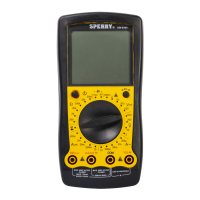
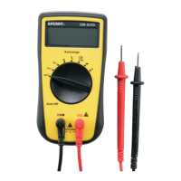
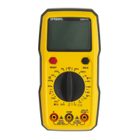
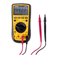
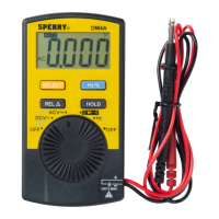
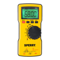
The Sperry Instruments DM6800 is a thin autoranging multimeter designed for various electrical measurements. It features a 1999-count LCD screen with a backlight for easy readability in different lighting conditions. The device is powered by two AAA batteries and has an auto power-off feature to conserve battery life, which can be disabled if continuous operation is required.

Function Description

The DM6800 offers a range of measurement functions, including AC/DC voltage, AC/DC current, resistance, and continuity.

Voltage Measurement (AC/DC): To measure AC voltage, the black test lead is inserted into the COM terminal and the red test lead into the INPUT terminal. The rotary switch is set to the AC voltage position. The test leads are then touched to the circuit under test. For AC voltage, the polarity of the test leads does not matter. It is recommended to touch one test lead to ground or neutral first, then the second to the hot wire. Typical AC voltage measurements include wall outlets, appliance outlets, motors, light fixtures, and switches.

For DC voltage measurement, the setup is similar: black test lead in COM, red test lead in INPUT, and the rotary switch set to the DC voltage position. When touching the circuit, the black (common) test lead should be connected to the negative DC source (ground) first, and the red (positive) test lead to the "live" source second. If the leads are reversed, a "-" indicator will appear on the display. Common DC voltage measurements include car batteries, automotive switches, motors, and household batteries. It is crucial not to measure voltages higher than 600V AC or DC to avoid personal injury or damage to the meter.

Current Measurement (AC/DC): For current measurements, the black test lead goes into the COM terminal, and the red test lead goes into the 10A terminal. The rotary switch is set to the current position. For AC current, the "SELECT" button is pressed until "AC" is shown on the display. Before measuring, power to the circuit must be turned off, and the circuit opened. The red test lead is connected to one side of the break, and the black test lead to the other. Polarity does not matter for AC current. After connecting, power is returned to the circuit, and the amps are read from the display.

For DC current, the process is similar. After setting the rotary switch to the current position, the "SELECT" button is pressed until "DC" is shown. With power off and the circuit open, the red test lead is connected to the positive side of the break, and the black test lead to the negative side. Power is then restored, and the amps are read. It is important not to measure currents exceeding 10A AC or DC. If the fuse burns out during measurement, the meter may be damaged or personal injury may occur. Continuous measurement for currents between 5-10 amps should not exceed 10 seconds, with a 15-minute wait before additional measurements.

Resistance Measurement: To measure resistance, ensure the power to the circuit is off. The black test lead is inserted into the COM terminal, and the red test lead into the INPUT terminal. The rotary switch is set to the Ω (ohms) position. The test leads are then touched to the resistor or non-energized component to be measured. Polarity is not a factor for resistance measurements. Typical resistance measurements include resistors, potentiometers, switches, extension cords, and fuses. For measurements greater than 1MΩ, the meter may take a few seconds to stabilize, which is normal for high resistance readings. If the input is not connected (open circuit), "OL" will be displayed.

Continuity Test: For continuity testing, disconnect circuit power and discharge any high-voltage capacitors before measuring. Do not input 60V DC or 30V AC. The black test lead goes into the COM terminal, and the red test lead into the INPUT terminal. The rotary switch is set to the continuity position. When the test leads are connected across the object being measured, the buzzer will sound continuously if the resistance is less than approximately 30Ω, indicating a good connection. If the resistance is greater than 100Ω, the buzzer will not sound, indicating a possible broken circuit. For resistances between 30Ω and 100Ω, the buzzer may or may not sound. Typical continuity measurements include switches, extension cords, and fuses. An open circuit will display "OL."

Usage Features

Display and Controls: The DM6800 features a clear LCD display that shows the measurement value, along with various symbols indicating the active mode or status.

  • Autorange: The meter automatically selects the appropriate measurement range.
  • MAX/MIN Button: Pressing this button once enters MAX mode, displaying the maximum reading. Pressing it again enters MIN mode, displaying the minimum reading. Holding the button down or turning the rotary switch exits this mode and clears stored readings.
  • HOLD Button: Pressing this button freezes the displayed value (Data Hold mode). Pressing it again resumes normal measurement.
  • SELECT Button: This button is used to switch between DC and AC current measurement functions.
  • BACKLIGHT Button: This button turns the backlight on or off. The backlight automatically turns off after 30 seconds to save battery power.
  • Rotary Switch: This is used to power the meter on/off and select the desired measurement function.

Safety Features: The meter is designed with safety in mind, conforming to CAT III 600V, Pollution Degree 2 standards. It includes overload protection with a 10A/600V fast fuse. Warnings are provided against measuring high voltages or currents, using the meter in the presence of flammable gases, or operating it with wet hands or damaged leads.

Maintenance Features

Battery Replacement: To avoid false readings and potential electric shock, the battery indicator will appear when the battery is low, signaling the need for replacement. To replace the batteries:

  1. Disconnect test leads from the circuit under test and from the meter's input terminals.
  2. Turn the meter off.
  3. Remove the screw from the battery cover on the back of the meter and slide the cover off.
  4. Replace the old batteries with two fresh AAA batteries. Rechargeable batteries should not be used in this unit.
  5. Carefully slide the battery cover back on and tighten the screw, being careful not to overtighten.

Fuse Replacement: If the fuse burns out, it must be replaced with a specified 10A/600V fast-type fuse (6.35mm x 32mm).

  1. Turn the meter off and remove test leads.
  2. Remove the five screws from the case bottom and separate the case top.
  3. Gently pry one end of the fuse loose and remove it from its bracket.
  4. Install the new fuse, ensuring it is firmly inserted into the fuse holder brackets.
  5. Rejoin the case bottom and top, and reinstall the five screws, taking care not to overtighten. Fuse replacement is seldom required; a burned fuse suggests improper operating procedures.

General Service:

  • The case should be periodically wiped with a damp cloth and mild detergent. Abrasives or solvents should not be used.
  • Terminals can be cleaned with a cotton swab and detergent to prevent dirt and moisture from affecting readings.
  • Always turn the meter off when not in use.
  • Remove the battery if the meter will not be used for a long time.
  • Avoid storing the meter in humid or high-temperature environments.

Sperry instruments DM6800 Specifications

General IconGeneral
ContinuityYes
Diode TestYes
Auto RangingYes
Data HoldYes
BacklightYes
DisplayLCD
DC Voltage Range600mV, 6V, 60V, 600V, 1000V
Temperature Range-40°C to 1000°C
Safety RatingCAT III

Related product manuals