EasyManua.ls Logo

SPI 40G03 - User Manual

SPI 40G03
2 pages
Print Icon
To Next Page IconTo Next Page
Loading...
IP65 DIGITAL INDICATORS
swissprec.com
1
Battery holder
12
SET mode icon
2
Data output Port
13
Out of lower tolerance icon
3
Stem
14
Within tolerance icon
4
Flat back
15
Out of upper tolerance icon
5
Contact point
16
TOL mode icon
6
Spindle
17
mm/INCH icon
7
LCD
18
MAX /MIN mode icon
8
Mode Button
19
ABS/INC icon
9
SET Button
20
Plus/Minus icon
10
ZERO/ON/OFF
21
Measuring direction icon
11
Low battery icon
IP65 DIGITAL INDICATORS
OPERATION MANUAL
SPI 40G03
IMPORTANT NOTICE
Clean all measuring surfaces and
body prior to use.
Clean the battery before
installation.
Zero set the tooling after installing
the battery.
Technical Specifications
Resolution: Inch: .0005”/.00005”,Metric: 0.01mm/0.001mm
Power: One silver oxide battery CR2032, 3V
Protection class IP65.
Working temperature: 0~ +40
Relative humidity: <80%
Storage temperature: -10~ +60
Contact point: carbide ball (#4-48UNF).
Operation
Zero Setting
When in ABS mode, press Zero/On.
The displayed value will change to zero unless a preset value
has been established.
Absolute and Incremental Modes
Absolute Mode: The absolute mode indicates that the
measurement is to the zero that has been previously set.
Incremental Mode: The incremental mode is provided as a
temporary zero at any point within the measuring range. The
Absolute zero previously set will be restored when the mode is
returned to absolute.
Switching between ABS and INC Modes
Short press the [SET] button to change the display to “INC”
(Incremental Mode). The reading will change to zero.
Short press the [SET] button again to return to “ABS” (Absolute
Mode). The reading will be returned to the original value.
Question and Answer IconNeed help?

Do you have a question about the SPI 40G03 and is the answer not in the manual?

Summary

Operation

Zero Setting

Sets the instrument to zero in ABS mode or allows for a preset value.

Absolute and Incremental Modes

Explains the difference between absolute and incremental measurement modes.

Switching between ABS and INC Modes

Details how to toggle between Absolute and Incremental measurement modes.

Switching between Mode Options

Describes how to access various mode options like tolerance and calibration.

Setting Tolerance Parameters

Guides on setting lower and upper tolerance limits for measurements.

Setting a Preset Value

Instructions for setting a specific measurement value as a reference point.

MAX;MIN Function

How to use the MAX/MIN functions to capture extreme measurement values.

Overview

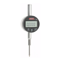
This document describes the IP65 Digital Indicator, a precision measuring device with various functionalities for accurate measurements.

Function Description

The IP65 Digital Indicator is designed for precise measurements, offering both absolute and incremental modes. It features a digital display (LCD) for clear readings and various icons to indicate the current mode, tolerance status, and measurement units. The device can display measurements in both millimeters (mm) and inches (INCH). It also includes a MAX/MIN function to record the maximum and minimum spindle movement values, and can calculate the difference between them. Tolerance settings allow users to define upper and lower limits, with visual indicators for values within, above, or below these tolerances.

Important Technical Specifications

  • Resolution:
    • Inch: .0005" / .00005"
    • Metric: 0.01mm / 0.001mm
  • Power: One silver oxide battery CR2032, 3V
  • Protection Class: IP65 (indicating protection against dust and water jets)
  • Working Temperature: 0°C to +40°C
  • Relative Humidity: <80%
  • Storage Temperature: -10°C to +60°C
  • Contact Point: Carbide ball (#4-48UNF)

Usage Features

The device is operated through several buttons:

  • Mode Button: Used to index flashing digits for preset values, switch between MAX/MIN modes, and change display signs.
  • SET Button: Used to select tolerance functions, change to upper tolerance, quit preset functions, and switch between ABS and INC modes.
  • ZERO/ON/OFF Button: Used to zero the display, turn the device on/off, select calibration functions, choose metric/inch units, select measurement direction, and choose digits for setting values.

Zero Setting:

  • In ABS mode, pressing the ZERO/ON/OFF button sets the displayed value to zero, unless a preset value is established.

Absolute and Incremental Modes:

  • Absolute Mode (ABS): Indicates measurements relative to a previously set zero point.
  • Incremental Mode (INC): Provides a temporary zero at any point within the measuring range. The absolute zero is restored when switching back to ABS mode.
  • Switching Modes: A short press of the SET button toggles between INC (displaying zero) and ABS (restoring the original value).

Switching Between Mode Options:

  • Long press of the SET button to select tolerance function.
  • Short press of the ZERO button to select calibration function.
  • Short press of the ZERO button to select Metric/Inch measurement unit.
  • Short press of the ZERO button to select measurement direction.

Setting Tolerance Parameters:

  • Long press of the SET button to select tolerance function.
  • Short press of the MODE button makes the right arrow and right digit flash.
  • Short presses of the ZERO button select digits for setting lower tolerance values and signs.
  • Short press of the SET button changes to upper tolerance, with the upper tolerance icon and last digit flashing.
  • Short presses of the ZERO button select digits for setting upper tolerance values and signs.

Setting a Preset Value:

  • Long press of the SET button, then short press of the ZERO button to select the CAL function.
  • Short press of the MODE button makes the last digit flash.
  • Short press of the MODE button indexes the flashing digit to the required preset value.
  • Short press of the ZERO button selects digits for setting the value.
  • Short press of the SET button quits the preset function. The preset value is loaded by pressing the ZERO button if ABS mode is selected.
  • Long press of the ZERO button removes a previously stored preset in CAL mode.

Change Display Sign:

  • Long press of the SET button, then short press of the ZERO button to index the menu to "dir."
  • Short press of the MODE button indexes the flashing display between plus and minus for inward spindle movement.
  • Short press of the SET button when the desired unit is flashing returns to measurement mode.

MAX/MIN Function:

  • MAX mode: Press the MODE button until "MAX" is displayed to show the maximum spindle movement. Press MODE again to exit.
  • MIN mode: Press the MODE button until "MAX" is displayed, then press the SET button to index to "MIN" mode to show the minimum spindle movement. Press MODE again to exit.
  • After collecting MAX and MIN data, press the SET button to display the difference between them. Press MODE to exit.

Maintenance Features

  • Cleaning: All measuring surfaces and the device body should be cleaned prior to use.
  • Battery Installation: The battery should be cleaned before installation.
  • Zero Setting After Battery Change: After installing the battery, the tooling should be zero-set.
  • Low Battery Warning: The display digits will fade or flash as the battery voltage diminishes. The display will fail completely upon total battery discharge. The battery should be replaced if these conditions occur.

SPI 40G03 Specifications

General IconGeneral
BrandSPI
Model40G03
CategoryMeasuring Instruments
LanguageEnglish

Related product manuals