• To detect a situation where it is either ground or no ground, we should use a Non-isolated
GPIO input
• In a situation where we need to detect a signal, either a voltage or a ground, we should use
an Isolated GPIO input.
• We should always make use of the Isolated GPIO input common ground pin when we want
to use an Isolated GPIO input
• The voltage or ground must be recognised by the Spider GPIO interface for it to work
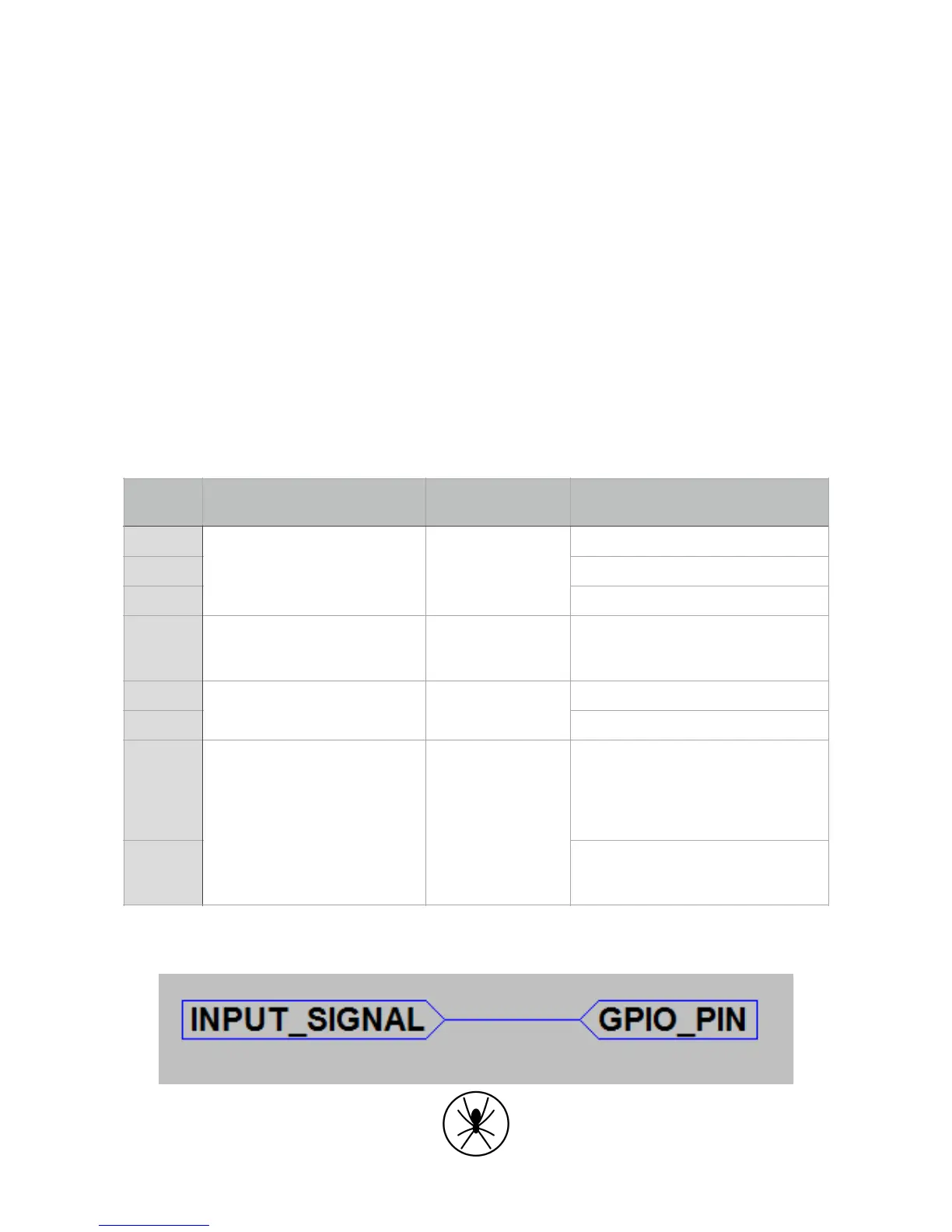
1.6.2. Input Signal Classification!
The following are suggested installations based on the above case numbers and associated input
signals.
Table 2: Input signal cases
Case 1:!
Pin 9 or Pin 10
Note in this case only one isolated
input pin can be used since pin 9 and
pin 10 share the common ground pin
8.