1.6.1. Pin Description!
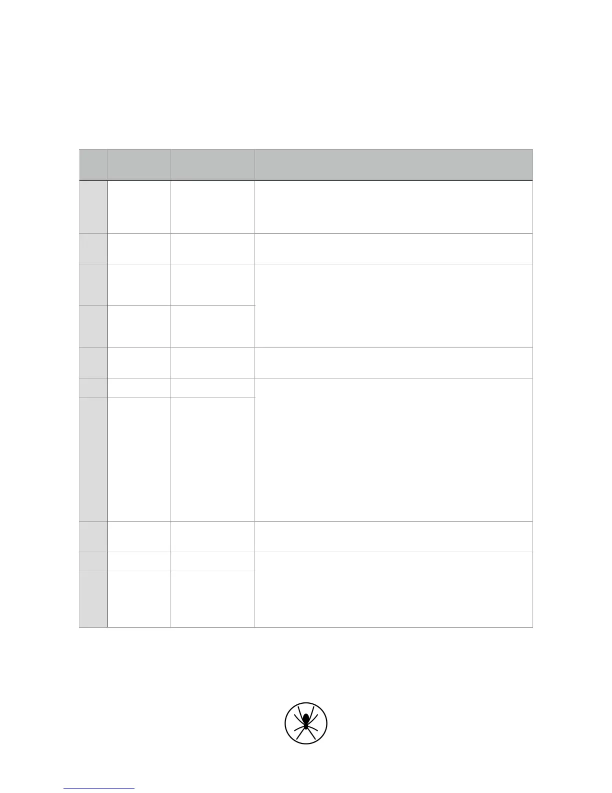
Table 1. GPIO pin descriptions
The Isolated GPIO input is quite different to the Non-isolated GPIO input:
Non-isolated +3.3
VDC voltage
signal
The +3.3VDC rail is intended to power such things as input
sensors
It is currently limited to 100mA to protect the Spider in the event
that this output is shorted
Non-isolated input
1 with basic
protection
The basic protection consists of current limiting resistors and
TVS diodes
There is provision for adjusting the default Low-Pass frequency
of 106kHz
Maximum voltage is +3.3 VDC
Non-isolated input
2 or analogue
input
The isolated outputs share a common ground connection. This is
separated from the Spider Ground
The isolated output has an#open collector#configuration. The
specification#must#be strictly followed.
An open collector output allows the 3rd party to pull the voltage
up to a large range of voltages and the Spider will drive this
voltage low to activate the output.
IMPORTANT
• Maximum voltage is +80 VDC
• Maximum current must be kept < 30 mA
• This is done by selecting an appropriate resistor
value
• Failure to limit the current and/or voltage will
result in#permanent#damage to that particular output port
The isolated inputs share a common ground connection. This is
separated from the Spider Ground
Voltage input range of +3.3 VDC ~ +12VDC (Absolute Max +15
VDC) without 620 ohm resistor.
Voltage input range of +9 VDC ~ +32VDC with 620 ohm resistor.
IMPORTANT
• Failure to limit the current and/or voltage will
result in#permanent#damage to that particular input port