www.spinning.com
7
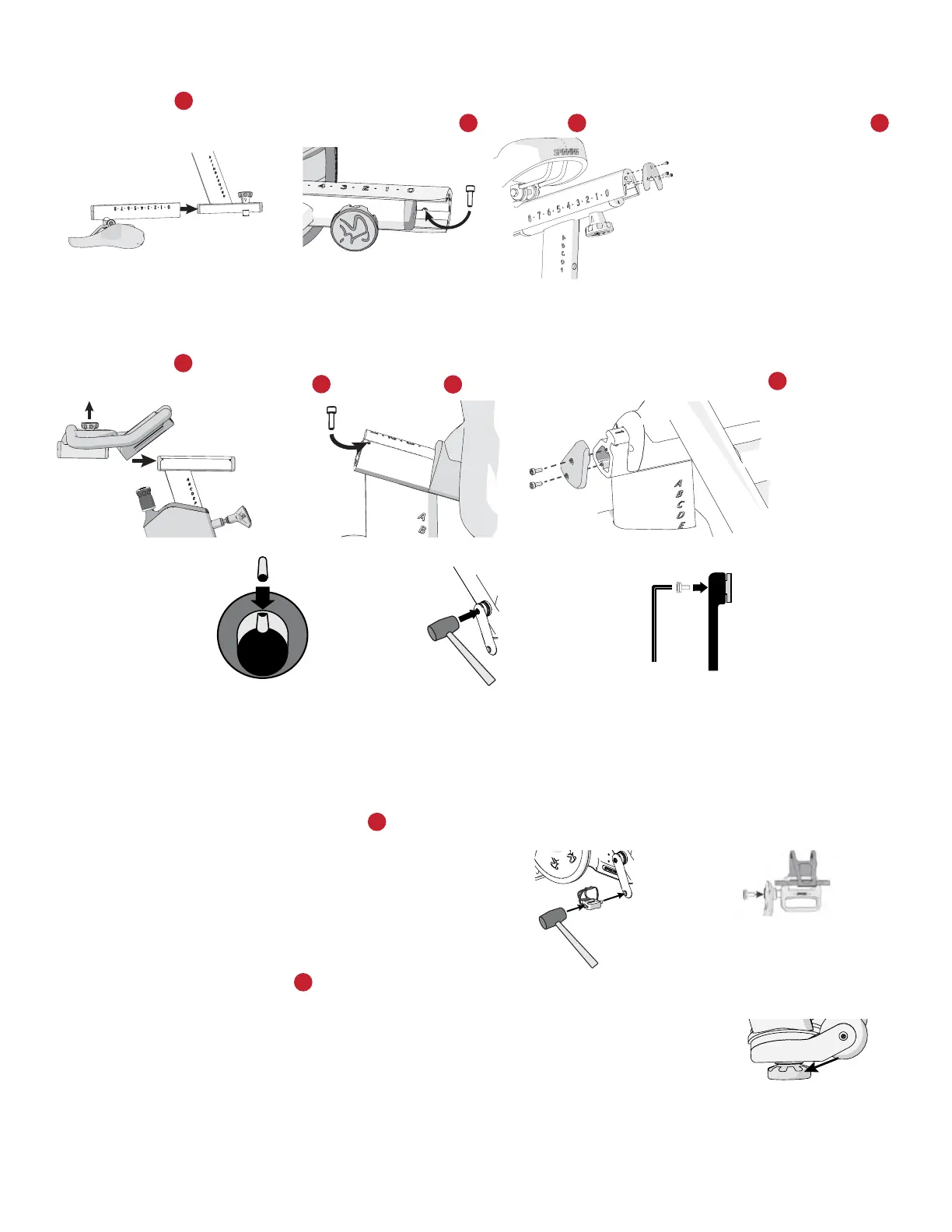
To attach the seat assembly:
1. Take the seat post out and turn it upside down. Slide the seat assembly onto the seat post (Figure 6)
2. Insert one bolt into the underside of the seat slider and fully tighten it to set the travel limit (Figure 7).
3. Reinstall the seat post and attach the seat slider end cap using 3 bolts (Figure 8) and fully tighten with a hex key.
To attach the handlebar assembly:
1. Position the handlebar assembly onto the handlebar post (Figure 9) by loosening the fore/aft handlebar knob and pulling it up to
align with the grooves on the handlebar post.
2. Insert one bolt into the post from either side and fully tighten it to set the travel limit (Figure 10).
3. Attach the handlebar post end cap using two bolts (Figure 11) and fully tighten with the hex key.
Attach the Crank
Locate the left side crank axle and note the notch that will accept the crank pin.
1. Place the crank pin into the slot on the bottom bracket axle (Figure C1).
2. Orient the corresponding notch on the crank and slide the crank onto the axle.
3. Use a rubber mallet to lightly tap the crank at the axle point onto the bottom bracket axle (Figure C2).
4. Secure the crank using the 8mm crank bolt and torque to 34-40 ft-lb (47-57 n-M) (Figure C3).
Attach the Pedals
Hold the pedals with the toe straps facing forward.
To attach the pedals:
1. Insert a pedal into its corresponding crank arm (Figure 12).
2. Use a rubber mallet to lightly tap the center of the pedal
into the crank arm to seat it (Figure 12).
3. Secure the pedal using one bolt (Figure 13) and torque to 33 ft-lb (45 N-m) with a hex key.
4. Repeat Steps 1-3 to attach the other pedal.
Level the Bike
Important: Place the equipment on a flat surface. Rotating the adjustable feet does not compensate
for extremely uneven surfaces. Make sure the bike is level before allowing anyone to use it.
To level the bike:
1. Try to rock the bike. If there is any movement, tip the bike to one side to locate the adjustable feet (Figure 14).
2. Correct the height of each adjustable foot by turning it clockwise (+) to lower the bike, or counterclockwise (-) to raise the bike.
3. When you are finished leveling the bike, place it on the floor. Recheck for movement and readjust as necessary.
3
38 5
5
3
4
10
9
3
Figure 6 Figure 7 Figure 8
Figure 9 Figure 10 Figure 11
Figure 12 Figure 13
Figure 14
1
Figure C1 Figure C2 Figure C3
 Loading...