IM-P006-07 CTLS Issue 12
22
Table 2 Recommended tightening torques for main valve seat item 18
Size of valve Size of socket across flats Tightening torques
DN15, DN15LC 30 mm A/F 110 - 120 N m
DN20 36 mm A/F 140 - 150 N m
DN25 41 mm A/F 230 - 250 N m
DN32 46 mm A/F 300 - 330 N m
DN40 — 400 - 490 N m
DN50 — 620 - 680 N m
DN80 — 600 - 700 N m
6. The seating faces of the main valve head and main seat may now be examined. If they are only slightly
worn both the main valve head and main seat may be lapped on a flat plate using a fine grinding paste.
'G' version: If there is wear or damage to the nitrile face then the head assembly must be replaced.
7. If either is badly worn or unfit for further use they will need to be replaced. However, as the seats and
valve heads are not supplied as matched pairs, it is not particularly necessary to replace both items.
8. Making sure that the thread and seating surface in the body are
clean refit the seat and tighten to the torque shown in Table 2.
9. Where a part has been fitted or where extensive lapping has
taken place, it will be necessary to reset the main valve pushrod
(26) to give the correct valve lift.
10. To do this it is necessary to expose the main diaphragm plate
and pushrod assemblyby following steps 2 and 3 in Section 5.8.
11. Refit the pushrod assembly and replace the main valve head
(17) making sure that it is located onto the main seat.
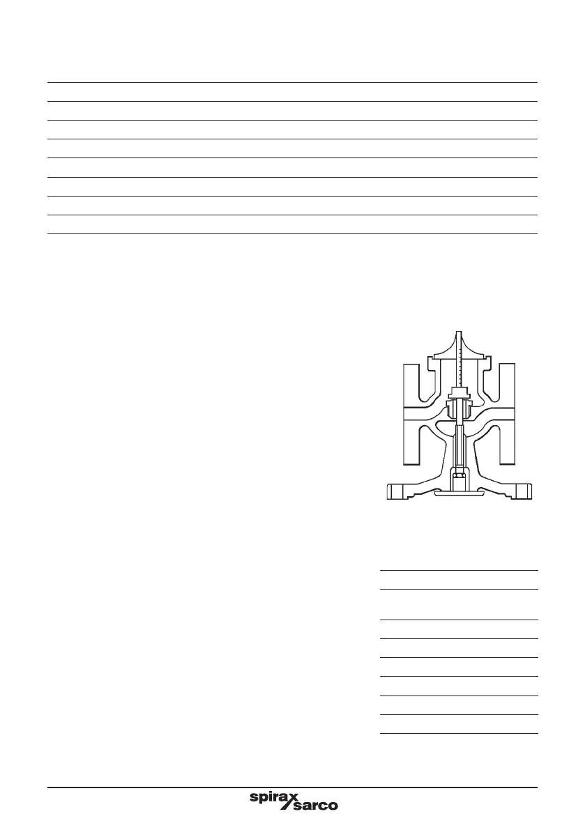
12. The main valve can now be opened by pushing on the plate (25)
until it comes up against the stop on the body. See Figure 11.
Check the valve lift by using a depth gauge as shown.
13. If the lift is different from that shown in the Table 3 below,
slacken the lock-nut (30) and adjust the lift by screwing the
pushrod (26) in or out of the main diaphragm plate (25). When
the lift is correct, retighten the lock-nut (30).
14. Replace the lower end of the valve by following the steps 5 to
8 in Section 5.8.
15. Make sure that the gasket faces on both the pilot valve block and
body are clean. Refit the main valve head (17) and replace the
main valve spring (16) correctly on top of the main valve head.
16. Fit new gasket (15) and secure the pilot valve block assembly
(10) onto the body withthe nuts (21). Tighten these nuts to the
torque shown in Table 1.
17. Refit 6 mm stainless steel pipework and retighten the union nuts
to ensure a steam tight seal.
18. Bring the valve back into commission by following as many steps
as are necessary in Section 4.1, 'Start-up'.
Fig. 11
Table 3
Size of valve Lift
DN15,
DN15LC
2.0 mm
DN20 2.5 mm
DN25 3.0 mm
DN32 3.5 mm
DN40 4.5 mm
DN50 5.0 mm
DN80 8.0 mm