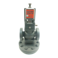
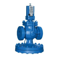
The Spirax Sarco FT43 and FT44 are ball float steam traps designed for efficient condensate removal in steam systems. These devices are crucial for maintaining plant efficiency by preventing steam locking and waterlogging.
Function Description
The FT43 (cast iron) and FT44 (carbon steel) ball float steam traps continuously remove condensate as it forms, ensuring that the steam system remains free of water. On start-up, a thermostatic air vent allows air to bypass the main valve, preventing air binding within the system. As hot condensate enters the main chamber, the float rises, and its attached lever mechanism opens the main valve, continuously draining condensate. When steam arrives, the float drops, closing the main valve. This continuous operation, combined with high start-up load handling capability, clean tight shut-off, and resistance to waterhammer and vibration, makes these traps highly effective.
Important Technical Specifications
General:
- Internals: Stainless steel working internals.
- Air Vent: Automatic built-in air venting facility.
- Connections: Integrally flanged connections for horizontal or vertical installations.
- Maintenance: Can be maintained without disturbing pipework.
- Flow Direction: Clearly marked on the trap body, varies by trap type and size.
- Compliance: Fully complies with Indian Boiler Regulations, 1950.
- Certification: Manufacturers' Typical Test Report available for FT44 (at extra cost).
FT43 (Cast Iron):
- Sizes: DN25, DN40, DN50.
- Flow Direction (Horizontal):
- DN25: Left to right (R-L versions available for DN25 FT43TV PN16 only).
- DN40 and DN50: Right to left.
- Flow Direction (Vertical): Downwards only.
- Standard Flanges: EN 1092 PN16, face-to-face dimensions in accordance with EN 26554 (Series 1).
- Optional Flanges: ASME B 16.5 Class 125 flanges available (tapped holes for flange bolts, UNC threads).
FT43 Pressure/Temperature Limits (PN16 Flange):
- PMA (Max Allowable Pressure): 13 bar g @ 195 °C.
- TMA (Max Allowable Temperature): 220 °C @ 12.1 bar g.
- Minimum Allowable Temperature: 0 °C.
- PMO (Max Operating Pressure for Saturated Steam Service): 13 bar g @ 195 °C (DN40 and DN50 traps limited to PMO equal to PMX).
- TMO (Max Operating Temperature): 220 °C @ 12.1 bar g.
- APMX (Max Differential Pressure):
- FT43-4.5: 4.5 bar.
- FT43-10: 10 bar.
- FT43-14: 13 bar.
- Cold Hydraulic Test Pressure: 19.5 bar g (with internals fitted, must not exceed PMX).
FT43 Pressure/Temperature Limits (ASME 125 Flange):
- PMA (Max Allowable Pressure): 13 bar g @ 90 °C.
- TMA (Max Allowable Temperature): 220 °C @ 9 bar g.
- Minimum Allowable Temperature: 0 °C.
- PMO (Max Operating Pressure for Saturated Steam Service): 10 bar g @ 184 °C (DN40 and DN50 traps limited to PMO equal to PMX).
- TMO (Max Operating Temperature): 220 °C @ 9 bar g.
- APMX (Max Differential Pressure):
- FT43-4.5: 4.5 bar.
- FT43-10: 10 bar.
FT44 (Carbon Steel):
- Sizes: DN15, DN20, DN25, DN40, DN50.
- Body and Cover Castings: Produced by a TÜV approved foundry.
- Flow Direction (Horizontal):
- DN15 to DN25: Left to right.
- DN40 and DN50: Right to left.
- Standard Flanges: ASME B 16.5 Class 150 and 300 flanges available with extended face-to-face dimensions.
FT44 Pressure/Temperature Limits (ASME 150 Flange):
- PMA (Max Allowable Pressure): 19.6 bar g @ 38 °C.
- TMA (Max Allowable Temperature): 300 °C @ 10.2 bar g.
- PMO (Max Operating Pressure): 13.9 bar g @ 198 °C.
- TMO (Max Operating Temperature): 266 °C @ 11.5 bar g (300 °C @ 10.2 bar g when fitted with a bimetallic air vent).
- Cold Hydraulic Test Pressure: 29.4 bar g.
- APMX (Max Differential Pressure):
- FT44-4.5: 4.5 bar (65 psi).
- FT44-10: 10 bar (145 psi).
- FT44-14: 14 bar (203 psi).
- FT44-21: 21 bar (304 psi).
- FT44-32: 32 bar (464 psi).
FT44 Pressure/Temperature Limits (ASME 300 Flange):
- PMA (Max Allowable Pressure): 40 bar g @ 100 °C.
- TMA (Max Allowable Temperature): 300 °C @ 27.5 bar g.
- PMO (Max Operating Pressure): 31.4 bar g @ 238 °C.
- TMO (Max Operating Temperature): 284 °C @ 28.5 bar g (300 °C @ 27.6 bar g when fitted with a bimetallic air vent).
- Cold Hydraulic Test Pressure: 60 bar g.
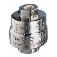
Air Vent Capsule (BP99/32):
- Suitable for use on 150 °C superheat @ 0 bar g (value reduces with elevated pressure).
- Bimetallic element fitted as standard to 32 bar variants for additional superheat resistance, available on other variants on request.
Usage Features
Installation:
- Safety First: Always observe safety information in Section 1 before installation.
- Product Suitability: Verify material suitability, pressure, temperature, and maximum/minimum values against intended use. Ensure safety devices are included if operating limits are lower than system limits.
- Flow Direction: Confirm correct installation situation and fluid flow direction, clearly marked on the trap body.
- Protection Removal: Remove all protection covers and film before installation.
- External Stresses: Spirax Sarco products are not designed to withstand external stresses; installers must take precautions to minimize them.
- Orientation: The trap must be fitted with the float arm in a horizontal plane, rising and falling vertically. Correct orientation can be visually checked by reading the writing on the body, cover, and name-plate.
- Drop Leg: Should be fitted below the steam system outlet with a small drop leg (typically 150 mm / 6") immediately preceding the trap to prevent steam flow over condensate under low load conditions.
- Steam Locking Prevention: Fit float traps as close as possible to the plant outlet. For applications with dip tubes or siphon pipes (e.g., rotating cylinders), an optional manually adjustable needle valve (SLR) can be fitted to prevent steam locking.
- SLR Adjustment: Opened by turning the spindle anticlockwise. Standard factory setting is 1½ turns (approx. 22 kg/h steam bypass @ 10 bar). Increase bypass flow by turning anticlockwise, reduce by turning clockwise.
- External Bypass: For high-speed cylinder applications requiring large blow-through steam, an external bypass with an adjustable needle valve is necessary.
- Exposed Positions: If in an exposed position, the trap should be lagged or drained by a separate small thermostatic trap (e.g., Spirax Sarco No.8, or Bydrain).
- Check Valve: Always fit a non-return (check) valve downstream when discharging into condensate return lines with back pressure to prevent steam space flooding.
- Maintenance Space: Ensure adequate space (200 mm / 8") is left to remove the cover for maintenance.
- Discharge Safety: If discharging to atmosphere, ensure it's a safe place as fluid may be 100 °C (212 °F).
Commissioning:
- After installation or maintenance, ensure the system is fully functioning and test any alarms or protective devices.
Maintenance Features
Safety:
- General: Observe 'Safety information' in Section 1 before any maintenance.
- Gasket Warning: The cover gasket contains a thin stainless steel support ring that can cause physical injury if not handled and disposed of carelessly.
- Qualified Personnel: Safe operation, installation, commissioning, use, and maintenance must be carried out by qualified personnel.
- Access & Lighting: Ensure safe access, working platforms, and adequate lighting.
- Hazard Assessment: Consider pipeline contents (flammable, hazardous, extreme temperatures) and surrounding environment (explosion risk, lack of oxygen, dangerous gases, hot surfaces, fire hazard, noise, moving machinery).
- System Impact: Assess the effect of proposed work on the complete system and personnel.
- Pressure & Temperature: Isolate and safely vent pressure. Allow time for temperature to normalize.
- Tools & Consumables: Use suitable tools and only genuine Spirax Sarco replacement parts.
- Protective Clothing: Wear appropriate protective clothing.
- Permits to Work: Comply with formal 'permit to work' systems or ensure a responsible person supervises.
- Handling: Assess risks for manual handling of large/heavy products and use appropriate methods.
- Residual Hazards: External surfaces can be very hot. Many products are not self-draining; take care during dismantling.
- Freezing: Protect non-self-draining products from frost damage.
- Disposal: Products are recyclable; no ecological hazard is anticipated with due care.
- Returning Products: Provide written information on any hazards, contamination, or mechanical damage.
Servicing:
- In-line Repair: Repairs can be carried out with the trap in the pipeline with suitable isolation.
- Reassembly: Ensure all joint faces are clean and the dowel locates correctly in the cover.
Main Valve Assembly (DN15, DN20, DN25):
- Unscrew support frame (9), pivot frame (10), and valve seat (5).
- Ensure seat/gasket faces are clean and dry.
- Fit new gasket (6) and valve seat (5) to the body (do not use gasket paste).
- Attach support frame (9) and pivot frame (10) to the body with assembly set screws (7), but do not tighten.
- Fit float arm (8) to pivot frame (10) using pin (11), centering valve head onto seat orifice.
- Tighten assembly set screws to recommended torques (Table 1).
Main Valve Assembly (DN40, DN50):
- Unscrew 4 bolts or nuts (7).
- Remove main valve assembly (5) and gasket (6).
- Ensure gasket faces are clean and dry.
- Fit new gasket (6) and main valve assembly (5), including the baffle plate (see Figures 10 and 11).
- Tighten bolts or nuts (7) evenly to recommended torques (Table 1).
Capsule Air Vent Assembly (DN15 to DN100):
- Remove spring clip, capsule, spacer plate, unscrew seat, and remove frame (17) and gasket (18).
- Ensure gasket faces are clean and dry.
- Fit new gasket (18), frame, and seat (17), tighten to recommended torque (Table 1).
- Assemble new spacer plate, capsule, and clip.
Bimetallic Air Vent Assembly (DN15 to DN100):
- Unscrew and remove element assembly (17) and gasket (18).
- Ensure gasket faces are clean and dry.
- Fit new gasket (18) and element assembly (17), tighten to recommended torque (Table 1).
Note: FT43 is not normally provided with a bimetallic air vent due to its PN16 rating, but can be made available on request.
FT Mechanisms (DN40 only) - Baffle Arrangement:
- A baffle plate is added over the inlet port to prevent flow from affecting float operation.
- When fitting, assemble the baffle plate under the mechanism retaining bolts.
FT Mechanisms (DN50 only) - Baffle Arrangement:
- Remove two uppermost studs; replace with longer studs provided.
- Assemble mechanism over the four studs.
- Place spacer collars then baffle plate over longer studs, resting on the back of the square flange.
- Replace nuts and tighten as normal.
Spare Parts:
- Available spares are shown in heavy outline in the diagrams.
- Order by description, trap size, type (horizontal/vertical), connection, and pressure range.
- For air vent assemblies, specify bimetallic or capsule type.
- For a complete overhaul, two of each spare are required.
Recommended Tightening Torques:
- Item 2 (Cover Nuts):
- DN15, DN20, DN25: 17 A/F, M10 x 30, 29-33 Nm (19-24 lbf ft).
- DN40: 24 A/F, M12 x 60, 60-66 Nm (44-48 lbf ft).
- DN50: 24 A/F, M16 x 70, 80-88 Nm (58-65 lbf ft).
- Item 5 (Main Valve Assembly):
- DN15, DN20, DN25: 50-55 Nm (37-40 lbf ft).
- Item 7 (Assembly Set Screws/Bolts/Nuts):
- DN15, DN20, DN25: M5 x 20, 2.5-2.8 Nm (1.8-2.1 lbf ft).
- DN40: 10 A/F, M6 x 20, 10-12 Nm (7.0-9.0 lbf ft).
- DN50: 13 A/F, M8 x 20, 20-24 Nm (15-17 lbf ft).
- Item 17 (Air Vent Assembly): 17 A/F, 50-55 Nm (37-40 lbf ft).
- Item 19 (Steam Lock Release Assembly): 22 A/F, 40-45 Nm (29-33 lbf ft).