INSTALLATION AND MAINTENANCE INSTRUCTIONS
IM-2-00021-US April 2014
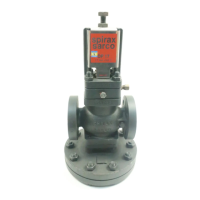
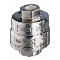
MST21 Series Thermostatic Steam Trap
Maximum Working Conditions
305 psig @572º F (21 barg @300º C)
Installation
1. Install strainer optional and isolation valve upstream of trap if draining to grade and both sides if
discharging into return system.
2. Never weld pipe connections to the trap, damage to the thermostatic capsule could result.
3. For freeze protection all drain lines must be pitched toward the trap for gravity ow. Trap must be
installed vertically discharging downward and discharge piping must be self-draining.
4. When used as a thermostatic air vent, the arrow pointed upwards. Locate at high point of main or
equipment, where air can collect and pipe discharge to a drain.
5. Always drain to a safe place.
Maintenance
1. Make sure all steam is turned off and pressure has been
dissipated before doing any work.
2. Remove cap (2) using a wrench.
3. Lift out the strainer screen (6), Spring (4), thermostat cap-
sule (3), and spacer plate (5).
4. Replace with new internals in the correct order. Make sure
the conical spring (4) is positioned with the narrow end in
contact with the capsule.
5. Fit a new gasket (7)
6. Ret the cap (2) using a little anti-seize compound on the
threads and tighten to the recommended torque (see table).
Size Lbf ft Nm
1/4” 73-80 100-110
3/8” 73-80 100-110
1/2” 73-80 100-110
3/4” 73-80 100-110
1” 73-80 100-110
Recommended Tightening Torques
1
Recommended for critical applications,
such as draining steam mains, tracing
lines, sterilizers and steam air venting.
Make sure trap is mounted in direction
of ow.
Spare Parts
• Complete internal set 3,4,5,6,7.
• Gasket Kit (set of 3) 7.
Note: Must choose either STD, NTS, or
Sub capsule.