EasyManua.ls Logo

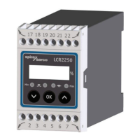
Spirax Sarco LCR2250 User Manual

Spirax Sarco LCR2250
24 pages
To Next Page IconTo Next Page
Page #1 background imageLoading...
Page #1 background image
IM-P693-01 EMM Issue 2
1
LCR2250 Level Controller
LCR2250
Level Controller
Installation and Maintenance Instructions
IM-P693-01
EMM Issue 2
850143-01
1. Safety information
2. General product information
3. Mechanical installation
4. Electrical installation
5. Commissioning
6. Fault finding
7. Technical information
8. Technical assistance
© Copyright 2020
Printed in Germany

Questions and Answers:

Spirax Sarco LCR2250 Specifications

General IconGeneral
ModelLCR2250
ManufacturerSpirax Sarco
ApplicationLevel Control
Input Signal4-20 mA
Enclosure RatingIP65
TypeController
Max. operating temperature150°C
MaterialsStainless steel
MountingPanel mount
OutputRelay
Output Signal4-20 mA
Power Supply24 V DC
Operating Temperature0 to 50°C
Communication ProtocolNot applicable

Summary

Safety Information

Directives and Standards

Details conformity to Low Voltage, EMC, and ATEX directives, and VdTÜV Bulletin for water level control.

General Product Information

Intended Use

Describes the application of the LCR2250 level controller in steam and water boiler systems and tanks.

Function

Explains the controller's operation with level transmitters, control valves, and output contacts.

Mechanical Installation

Dimensions

Provides physical dimensions and a diagram of the LCR2250 level controller.

Installation in Control Cabinet

Details how to mount the controller onto a standard support rail in a control cabinet.

Electrical Installation

Wiring Diagram

Presents a detailed wiring diagram for connecting the LCR2250 level controller.

Supply Voltage Connection

Explains requirements for connecting the 24 Vdc SELV power supply and fitting a fuse.

Connection of Output Contacts

Details wiring for the output contacts and handling of inductive loads.

Connecting the Level Transmitter

Specifies cable requirements and connection method for the level transmitter.

Connection of Actual Value Output

Describes how to connect the screened cable for the 4-20 mA actual value output.

Tools

Lists the required insulated screwdriver for electrical installation.

Connection of Level Transmitter

Details connecting the level transmitter, with emphasis on cable and screen routing.

Commissioning

Factory Settings

Lists the default configuration parameters set at the factory for the controller.

Changing Factory Settings

Provides a safety warning before modifying factory settings.

Changing Function and Input of Level Transmitter

Explains how to access and change code switch settings for transmitter input and function.

Meaning of Codes on 7-Segment Display

Defines codes displayed during operation, parameterization, and fault conditions.

Setting the Measuring Range

Details how to set the lower and upper limits of the measuring range on the transmitter.

Setting Parameters

Describes the procedure for navigating and changing device parameters using the push buttons.

Setting Switchpoints and Control Parameters

Guides on setting MIN/MAX switchpoints, setpoint, proportional band, and integral action time.

Displays

Explains the meaning of LED indicators and display states during operation.

Check Function of MIN/MAX Output Contacts

Describes the test procedure for verifying the MIN/MAX alarm output contacts.

Fault Finding

Display, Diagnosis and Troubleshooting

Provides guidance on checking supply voltage, wiring, and interpreting fault codes.

Technical Assistance

Returning Faulty Equipment

Provides instructions and required information for returning faulty equipment for service or warranty.

Related product manuals