EasyManua.ls Logo

Spirax Sarco 1600V User Manual

Spirax Sarco 1600V
16 pages
To Next Page IconTo Next Page
Page #1 background imageLoading...
Page #1 background image
SOFTWARE VERSION 3.0x
code 80086 / Edition 0.5 - 01/2001
ISO 9001
1600V / 1800V
CONTROLLER FOR VALVE
USERS’ MANUAL
1
1 • INSTALLATION
• Dimensions and cut-out; panel mounting
CE MARKING:
EMC conformity (electromagnetic compatibility) with EEC Directive
89/336/CEE with reference to the generic Standard EN50082-2 (immunity in industrial
environments) and EN50081-1 (emission in residential environments). BT (low voltage)
conformity respecting the Directive 73/23/CEE modified by the Directive 93/68.
Limitations: the 1800V model conforms to EN55011 standard for radiated emissions in
industrial environment.
MAINTENANCE:
Repairs must be carried out only by trained and specialised
personnel. Remove the power to the instrument before accessing the internal parts.
DO NOT clean the case with solvent (trichlorethylene, petrol, etc.). The use of such
solvents can have adverse effects on the mechanical reliability of the instrument. To
clean the plastic case please use a clean cloth with ethilic alcohol or water.
SERVICE:
SPIRAX-SARCO has a service department.The guarantee excludes defects
caused by usage that does not conform to the instructions.
2 • TECHNICAL SPECIFICATIONS
FUNCTION CABLE TYPE LENGTH
Power supply cable 1 mm
2
1 mt
Relais output cable 1 mm
2
3,5 mt
Digital communication wires 0,35 mm
2
3,5 mt
C.T. connection cable 1,5 mm
2
3,5 mt
TC input 0,8 mm
2
compensated 5 mt
Pt100 input 1 mm
2
3 mt
The EMC conformity has been tested with the following connections
96
115
108
96
113
10
92
92
115
48
70
115
44,5
92
113
10
108
96
To ensure a correct
installation, heed the
warnings in the
manual
Panel mounting:
To fix the instrument, insert the brackets provided into the seats on either side of the
case. To mount two or more instruments side by side, respect the cut-out dimensions
shown in the drawing. In order to get the IP65 protection, take the instruments out from
its case and apply the supplied gasket of the front edge of the case itself using some
adhesive. The replace the instruments inside the case.
!
RTD type (scale configurable within
indicated range, with or without decimal point
PTC type (on request)
DIN 43760 (Pt100, JPT100)
990, 25°C
Max line resistance for RTD
20
Safety
detection of short- or open-circuit probe,
LBA alarm, HB alarm
°C / °F selection
faceplate configurable
Linear scale ranges
-1999 to 9999 with configurable decimal point position
Thermocouples
IEC 584-1 (J, K, R, S, T, B, E, N, Ni-Ni18Mo, L NiCr-CuNi)
Cold junction error
0,1° / °C
Control terms
PID, Auto-tune, on-off
pb / dt / di
0.0 ... 999.9% / 0.00 ... 99.99min / 0.00 ... 99.99min
Control actions
Heat / Cool
Control outputs
on / off, pwm, Apri / Chiudi
Cycle time
0.1 ... 200 sec
Main output type
Relay, Logic, Continuous (optional)
Softstart
0.0 ... 500.0 min
Maximum power limit heat / cool
0.0 ... 100.0 %
Fault power setting
-100.0 ... 100.0 %
Automatic blanking
Optional exclusion, displays PV value
Configurable alarms
3 configurable alarms of type: high, low, deviation,
absolute or relative, LBA, HB
Alarm masking
- exclusion during warm up
- latching reset from faceplate or external contact
Type of relay contact
NO (NC), 5A, 250V, cosϕ = 1
Faceplate protection
IP65
Working / Storage temperature range
0...50°C / -20...70°C
Relative humidity
20 ... 85% Ur non condensing
Installation
Panel, plug-in from the front
Weight
400g (1600V); 600g (1800V) in complete version
Main input
TC, RTD (Pt100 - JPT100), PTC,
60mV, Ri 1M, 10V, Ri 10K, 20mA, Ri = 50
CT scale range
configurable from 0, ... , 100.0A
Transmitter power (optional)
filtered 10 / 24Vdc, max 30mA
short-circuit protection, isolation 1500V
Analogue retransmission signal
(optional)
10V / 20mA, isolation 1500V
Logic inputs (optional)
24V NPN, 4.5mA; 24V PNP, 3.6mA
isolation 1500V
Serial interface (optional)
CL; RS422/485; RS232; isolation 1500V
Baude rate
1200 ... 19200
Protocol
GEFRAN / MODBUS
Logic output for static relay
11Vdc, Rout = 220 (6V/20mA)
(option) remote set-point or
Ammeter input
Feed-back input
Valve position from potentiometer
0 ... 10V, 2 ... 10V, Ri 1M
0 ... 20mA, 4 ... 20mA, Ri = 5
Potentiometer > 500,
CT 50mAac, 50/60Hz, Ri = 1,5,
isolation 1500V
Power supply (switching type)
(std) 100 ... 240Vac/dc ±10%; 50/60Hz, 12VA max
(opz.) 20...27Vac/dc ±10%; 50/60Hz, 12VA max
Display
2 x 4 digits green of height 10 and 7mm (1600V),
20 and 13mm (1800V)
Keys
5 mechanical keys (*, Man/Auto, INC, DEC, F)
Accuracy
0.2% full scale a 25°C ambient temperature
SPIRAX SARCO Srl
Via Pasubio, 8
20063 Cernusco sul Naviglio
Tel. +39 02.92119511 - Fax +39 02.9240321
Question and Answer IconNeed help?

Do you have a question about the Spirax Sarco 1600V and is the answer not in the manual?

Spirax Sarco 1600V Specifications

General IconGeneral
BrandSpirax Sarco
Model1600V
CategoryController
LanguageEnglish

Summary

Installation Guide

Dimensions and Panel Mounting

Details on instrument dimensions and panel mounting procedures.

Technical Specifications Overview

Faceplate Description and Controls

Function Indicator Overview

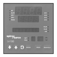
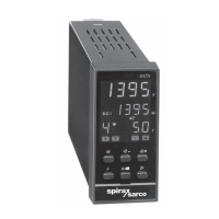
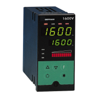
Explains indicators for operation modes and system states.

Process Variable (PV) Display

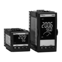
Shows the current process variable and error messages.

Setpoint (SV) Display

Displays the current setpoint value.

Bargraph Indicator

Visual representation of a variable as a percentage.

Function and Special Keys

Details on the 'F' key and '*' key functions.

Connection Guide

Power Supply Connections

Details standard and optional power supply connections.

Output Connections

Describes generic and analogue output connection configurations.

Transmitter Supply Connection

Details the isolated transmitter supply connection.

Digital Input Connections

Explains isolated digital input connection specifications.

Auxiliary Input Connections

Describes auxiliary inputs and current transformer connections.

Serial Line Connection

Details serial line connection configurations for communication.

Input Type Connections

Lists available input types like thermocouples and RTDs.

Programming and Configuration

INFO Menu

Displays information like serial code and software version.

dAtA Menu

Accesses custom menus for data configuration.

CFG Menu

Used for configuring control parameters.

SEr Menu

Configuration for serial communications.

InP Menu

Settings related to input configurations.

Out Menu

Configuration of output settings.

Protection Code (Prot)

Protection code settings for the instrument.

Hardware Configuration (Hrd)

Hardware configuration settings.

Input Linearisation (Lin)

Input linearisation settings.

Custom Data (CuSt)

Custom data menu.

User Calibration (U.CAL)

User calibration options.

Control Actions and Parameters

Notes on Control Actions

Explains Proportional, Derivative, and Integral control actions.

Tuning and Calibration Procedures

Manual Tuning Guide

Step-by-step guide for manually tuning PID parameters.

Software On/Off Switching

Procedure for disabling/enabling the instrument's power function.

Advanced Control Functions

Self-Tuning Function

Automatic calculation of PID parameters for optimal control.

Auto-Tuning Function

Continuous or one-shot tuning for system oscillation reduction.

Control Output Modes

Details on proportional-only and relative gain heat/cool control.

Alarm Functions

Alarm Types and Behavior

Describes absolute, deviation, and symmetrical alarm configurations.

HB Alarm Function

Monitors load current variations using a current transformer.

LBA Alarm Function

Detects control loop interruptions, like broken heaters.

Soft-Start Function

Gradually increases output power upon instrument startup.

Specialized Functions

Timer and Setpoints Functions

Configuration and operation of timers and multiple setpoints.

Multiset Function and Setpoint Gradient

Enables multiple setpoints and controls setpoint change ramps.

Motorized Valve Control

Valve Control Parameters

Defines parameters like actuator time, minimum pulse, and dead band.

Valve Control Types

Details floating and feedback valve control types (V0, V1, V2).

Input Correction and Accessories

Main Input Correction Function

Allows custom correction of main input readings via four values.

Current Transformer Accessory

Details current transformers for current measurements.

RS232 Interface Cable

Description of RS232 cable for PC configuration.

Order Code and Warnings

Product Order Code Configuration

Guide to configuring the instrument's order code.

Safety Warnings and Precautions

Critical safety advice for installation and operation.

Related product manuals